A pneumatic wave energy generator

A power generation device, wave energy technology, applied in ocean energy power generation, engine components, machines/engines, etc., can solve problems such as inability to use large-scale power generation

Active Publication Date: 2018-08-14
济南海川投资集团有限公司
View PDF6 Cites 1 Cited by
  • Summary
  • Abstract
  • Description
  • Claims
  • Application Information

AI Technical Summary

Problems solved by technology

[0002] The currently used or applied patents for ocean wave power generation devices are only suitable for small-scale power generation and cannot be used for large-scale power generation

Method used


Image

  • A pneumatic wave energy generator
  • A pneumatic wave energy generator
  • A pneumatic wave energy generator

Examples


Embodiment Construction

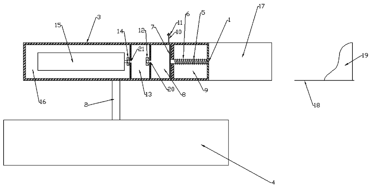
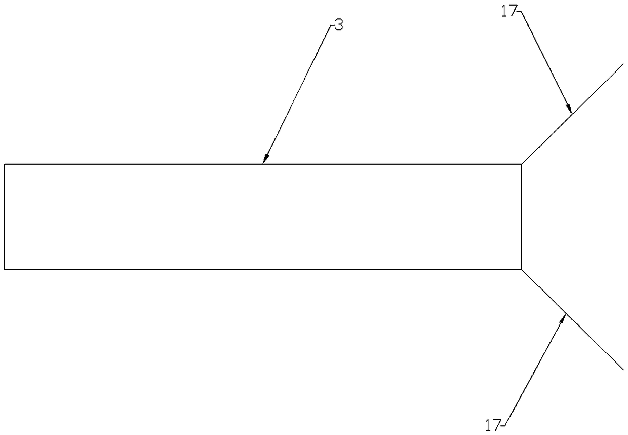
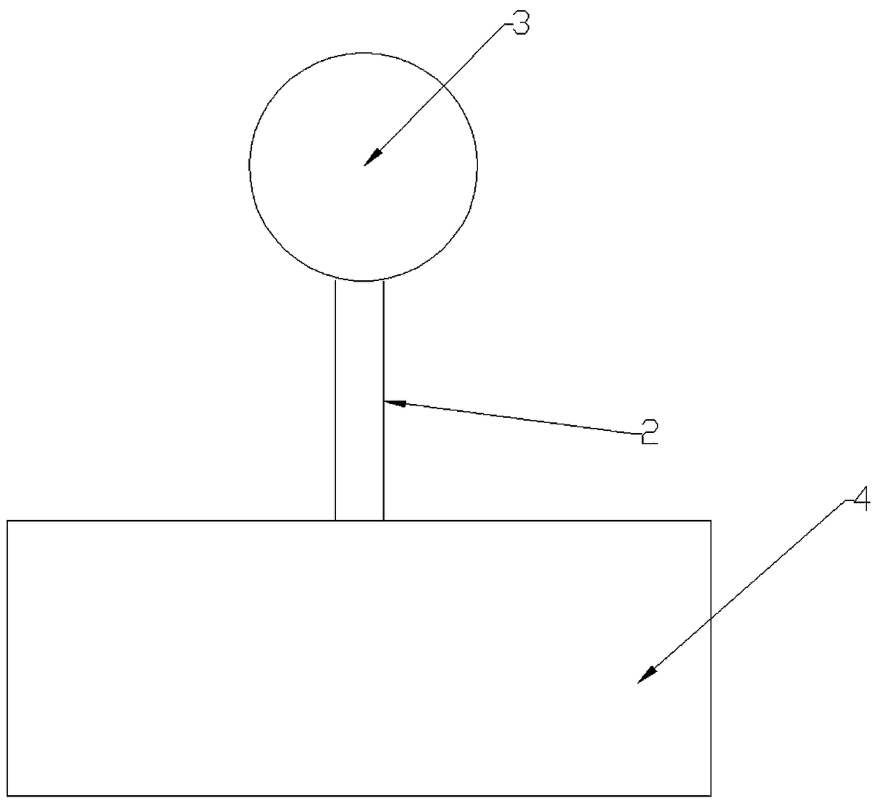
[0008] The pneumatic wave energy generating device is mainly composed of a push plate 1, a rotating rod 2, a casing 3, a buoyancy tank 4, a push rod 5, a spring 6, a piston 7, a pneumatic cylinder 8, a push chamber 9, an air intake pipe 10, an air intake unit Directional valve 11, one-way valve 12, energy storage chamber 13, constant pressure valve 14, generator set 15, generator chamber 16, deflector 17, hole A20, hole B21; one end of spring 6 is fixed to push plate 1, and the spring The other end of 6 is fixed with the right side of push chamber 9; push rod 5 passes through spring 6, its right end is fixed with push plate 1, and the left end passes through the hole of push chamber 9 and is fixed with piston 7; the right side of energy storage chamber 13 has a hole A20 communicates with the pneumatic cylinder 8, and the left side of the energy storage chamber 13 has a hole B21 which communicates with the generator chamber 16. The valve 12 enters the energy storage chamber 13;...


PUM


Abstract

The invention provides a pneumatic type wave energy power generation device which is mainly used for ocean wave energy power generation. According to the pneumatic type wave energy power generation device, large-scale power generation can be achieved, the quantity of generated power is stable, and the power generation device can be directly connected to the national power grid. The pneumatic type wave energy power generation device is mainly composed of a pushing plate 1, a rotating rod 2, a shell 3, a floating box 4, a pushing rod 5, a spring 6, a piston 7, a pneumatic cylinder 8, a pushing chamber 9, an air inlet pipe 10, an air inlet one-way valve 11, a one-way valve 12, an energy storage chamber 13, a constant pressure valve 14, a generator set 15, a generator chamber 16, a deflector 17, a hole A 20 and a hole B 21. The main operating principle of the pneumatic type wave energy power generation device is that sea waves impact the pushing plate 1 to move to the left, the pushing plate 1 pushes the piston 7 to move to the left through the pushing rod 5 so that air in the pneumatic cylinder 8 can be compressed and fed into the energy storage chamber 13, and the compressed air in the energy storage chamber 13 is subjected to equal-pressure releasing through the constant pressure valve 14 to blow a rotor of the generator set 15 to rotate, so that a generator generates power.

Description

technical field [0001] The invention is mainly used for ocean wave power generation. Background technique [0002] The currently used or applied patents for ocean wave power generation devices are only suitable for small-scale power generation and cannot be used for large-scale power generation. Contents of the invention [0003] The invention can generate electricity on a large scale and the electricity generated is stable, and can be directly connected to the national grid; 5), spring (6), piston (7), pneumatic cylinder (8), push chamber (9), intake pipe (10), intake check valve (11), check valve (12), energy storage chamber (13), constant pressure valve (14), generator set (15), generator chamber (16), deflector (17), hole A (20), hole B (21); spring (6) one end and The push plate (1) is fixed, the other end of the spring (6) is fixed to the right side of the push chamber (9); the push rod (5) passes through the spring (6), its right end is fixed to the push plate (1)...

Claims


Application Information

Patent Timeline
Patent Type & Authority Patents(China)
IPC IPC(8): F03B13/24
CPCF03B13/24Y02E10/30
Inventor 彭宝安
Owner 济南海川投资集团有限公司
Why Eureka
Try Eureka