Throttling structure for long-distance pipeline

A long-distance pipeline and flow channel technology, applied in the field of gas regulating devices, can solve problems such as gas transmission stagnation, gas reverse channeling, etc., and achieve the effects of reducing resistance, reducing weight, and convenient and flexible adjustment

Inactive Publication Date: 2016-12-21
CHENGDU GUOGUANG ELECTRONICS INSTR
View PDF6 Cites 6 Cited by
  • Summary
  • Abstract
  • Description
  • Claims
  • Application Information

AI Technical Summary

Problems solved by technology

[0003] The gas pipeline is the extension leg of the pipeline gas transmission station. During the natural gas transmission process, the gas flow in the pipeline is unstable, which will continuously scour the pipeline wall during the long-distance transmission. At the same time, when the injected gas volume is relatively small , the gas in the pipeline on the way of transmission will also appear back channeling and other imaginations, which will lead to the stagnation of gas transmission

Method used


Image

  • Throttling structure for long-distance pipeline

Examples


Embodiment 1

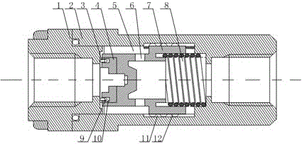
[0020] Such as figure 1 As shown, this embodiment includes a valve body 2, a tubular movable block 7 with one end closed, and a connecting head 1 whose end extends to the inside of the valve body 2. The connecting head 1 communicates with the inside of the valve body 2, and the closed end of the movable block 7 The outer diameter is smaller than the outer diameter of the open end, and there is a chute on the inner wall of the middle part of the valve body 2, and the open end of the movable block 7 is slidably arranged in the chute, and the annular space between the closed end of the movable block 7 and the chute forms a flow channel 5 , a contact block 4 is provided on the closed end face of the movable block 7, a packing ring 3 is provided on the extension end of the connecting head 1, and a protruding part 9 is installed on the packing ring 3, and the protruding part 9 It is an elastic rubber block with a triangular shape, and on the end surface of the contact block 4, there...


PUM


Abstract

The invention discloses a throttling structure for a long-distance pipeline. The throttling structure comprises a valve body, a movable block and a connector, wherein the connector communicates with the interior of the valve body. The outer diameter of the closed end of the movable block is smaller than the outer diameter of the open end of the movable block, a sliding groove is formed in the inner wall of the middle of the valve body, the open end of the movable block is arranged in the sliding groove in a sliding mode, a hollow flow channel is formed between the closed end of the movable block and the sliding groove, a contact block is arranged on the end face of the closed end of the movable block, a packing ring is arranged at the extension end of the connector, a circular groove matched with the packing ring and a protruding part is formed in the end face of the contact block, the movable block is provided with a gas outlet hole communicating with the flow channel, and a spring is installed between a circular protrusion and the open end of the movable block. When the gas flow is unstable, the movable block is continuously adjusted under the supporting effect of the spring, and therefore the gap between the connector and the contact block can be matched with the flow rate of injected gas, and automatic control over the injected gas can be realized.

Description

technical field [0001] The invention relates to a gas regulating device, in particular to a throttling structure for long-distance pipelines. Background technique [0002] Pipeline gas transmission station is a variety of operation stations established for pipeline transportation of natural gas or petroleum associated gas. According to the location of the compressed gas station along the pipeline, it is divided into a starting gas compressor station, an intermediate gas compressor station and a terminal gas filling station. The starting point compressor station is located near the gas gathering center or processing plant of the gas field, providing pressure energy for natural gas, and performing operations such as gas purification, gas mixing, pressure regulation, gas metering, and pig delivery. The intermediate compressor station is located along the transportation pipeline, mainly to pressurize the natural gas that consumes pressure energy during transportation. The term...

Claims


Application Information

Patent Timeline
Patent Type & Authority Applications(China)
IPC IPC(8): F16K17/34
CPCF16K17/34
Inventor 吕忠贵
Owner CHENGDU GUOGUANG ELECTRONICS INSTR
Why Eureka
Try Eureka