Redundant structure vortex flowmeter

A technology of vortex flowmeter and redundant structure, which is applied in the direction of volume/mass flow generated by mechanical effect, and through detecting the dynamic effect of fluid flow, etc., which can solve the adverse effects of enterprises, affect the production process, and ordinary flowmeters cannot separate Problems such as two-way signals can improve detection accuracy and stability and reduce on-site construction costs

Inactive Publication Date: 2016-12-21
JIANGSU WEIYI ELECTRONICS
View PDF6 Cites 0 Cited by
  • Summary
  • Abstract
  • Description
  • Claims
  • Application Information

AI Technical Summary

Problems solved by technology

Since ordinary flowmeters cannot separate two signals, two flowmeters need to be installed at such important measuring points, and the installation of two flowmeters requires a straight pipe section at least 30 times the diameter of the pipe between the two flowmeters. However, this requirement cannot be met in the industrial field.
[0003] Furthermore, the industrial production process is a continuous process, and the failure of any part will affect the entire production process, thereby adversely affecting the enterprise
In the flow detection process of the pipeline, the flow meter often fails due to changes in external conditions or other factors. The faulty flow meter cannot transmit the correct flow signal, which affects the production of the enterprise. , the flowmeter can only be repaired and replaced during overhaul or production shutdown, which also brings a relatively large adverse effect to the enterprise

Method used


Image

  • Redundant structure vortex flowmeter

Examples


Embodiment 1

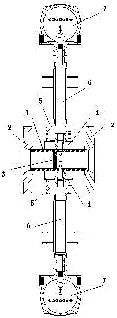
[0011] Embodiment 1: A vortex flowmeter with a redundant structure, including a flowmeter pipeline 1, a connecting flange 2 installed at both ends of the flowmeter pipeline 1, a vortex generator 3 arranged in the flowmeter pipeline 1, and a vortex generator Two symmetrical sensors 4 are arranged on the rear side of the body 3, and the two sensors 4 are arranged symmetrically up and down and spaced apart. , the sensor 4 exposed to the outer end of the flowmeter pipeline 1 is installed in the flowmeter housing 5, the flowmeter housing 5 is connected to the bracket 6, and the bracket 6 is connected to the flowmeter head 7. One of the sensors 4 is connected to the DCS through an electronic circuit for normal production control; the other sensor 4 is connected to the ESD through an electronic circuit for an emergency shutdown system.

Embodiment 2

[0012] Embodiment 2: With reference to Embodiment 1, two sensors 4 are simultaneously connected to the DCS through an electronic circuit, and the deviation of the two signals ±1% is used as a diagnostic means to improve detection accuracy.

Embodiment 3

[0013] Embodiment 3: Referring to Embodiment 1, one is for standby and the other is for use. When one of the sensors is damaged, the other can detect and provide accurate flow signals, which improves the stability of enterprise production.


PUM


Abstract

The invention provides a redundant structure vortex flowmeter comprising a flowmeter pipeline, connecting flanges installed on both ends of the flowmeter pipeline and a vortex generating body arranged in the flowmeter pipeline, wherein two symmetrical sensors are arranged on a rear side of the vortex generating body, probes of the two sensors stretch into the flowmeter pipeline, outer ends of the sensors exposed from the flowmeter pipeline are installed in a flowmeter shell, the flowmeter shell is connected with a bracket, and the bracket is connected with a flowmeter header. Two relatively independent sensors are arranged on one flowmeter, thereby greatly reducing the on-site construction cost, improving the accuracy and stability of detection and being suitable for industrial production.

Description

technical field [0001] The invention relates to the field of manufacturing vortex flowmeters. Background technique [0002] In some important measuring points in industrial production, such as the nitro compound fertilizer project, the ratio of raw materials is very strict. Once the allowable error is exceeded, it may cause safety accidents, so the measurement requirements for such measuring points Extremely strict. Two signals need to be designed, one is connected to DCS for normal production control, and the other is connected to ESD. When the data is abnormal, the ESD system will stop in an emergency to ensure production safety. Since ordinary flowmeters cannot separate two signals, two flowmeters need to be installed at such important measuring points, and the installation of two flowmeters requires a straight pipe section at least 30 times the diameter of the pipe between the two flowmeters. However, this requirement cannot be met in the industrial field. [0003] Fu...

Claims


Application Information

Patent Timeline
Patent Type & Authority Applications(China)
IPC IPC(8): G01F1/32
CPCG01F1/32
Inventor 唐贤昭李洋
Owner JIANGSU WEIYI ELECTRONICS
Why Eureka
Try Eureka