Method for implementing fabricated concrete house building by using members with novel connecting ends

A concrete and prefabricated technology, applied in the direction of building components, buildings, building materials, etc., can solve the problems of large investment in concrete prefabricated component processing plants, difficulties in market acceptance, and structural hidden dangers

Pending Publication Date: 2022-04-19
万平华 +2
View PDF0 Cites 0 Cited by
  • Summary
  • Abstract
  • Description
  • Claims
  • Application Information

AI Technical Summary

Problems solved by technology

[0005] 1. The design and production of components have not yet been standardized, so there are a large number of components; components include various large prefabricated components, not only the cost of mold making is high, resulting in high cost of prefabricated parts, but also the transportation of large prefabricated parts Larger vehicles and some special brackets are required, and the additional transportation costs further increase the cost of building the house; the production of large-scale and various prefabricated reinforced concrete components determines the large investment of the concrete prefabricated component processing plant, which furt

Method used


Image

  • Method for implementing fabricated concrete house building by using members with novel connecting ends
  • Method for implementing fabricated concrete house building by using members with novel connecting ends
  • Method for implementing fabricated concrete house building by using members with novel connecting ends

Examples


Embodiment Construction

[0021] Below, in conjunction with accompanying drawing, specifically describe how to implement building house according to the present invention:

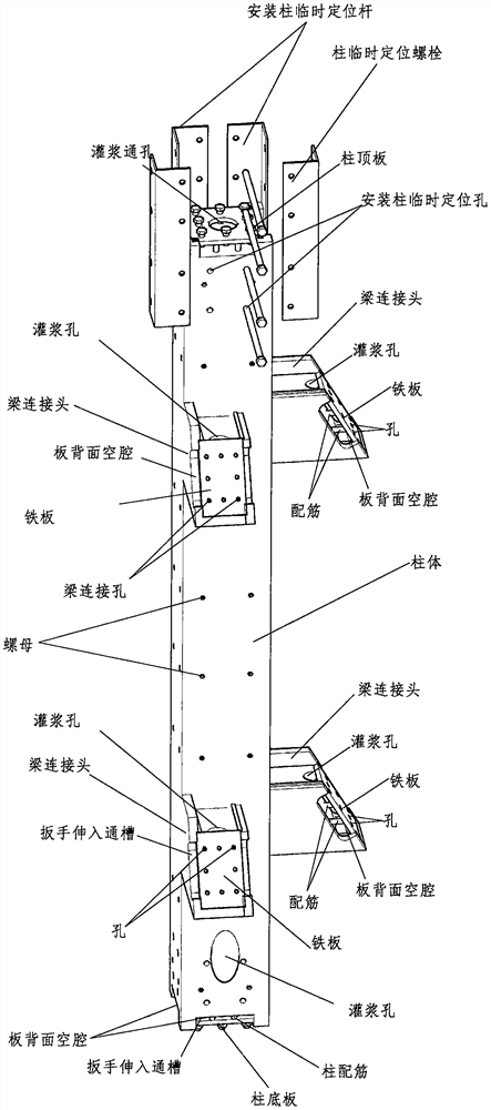
[0022] figure 1 The characteristics of the column are as follows:

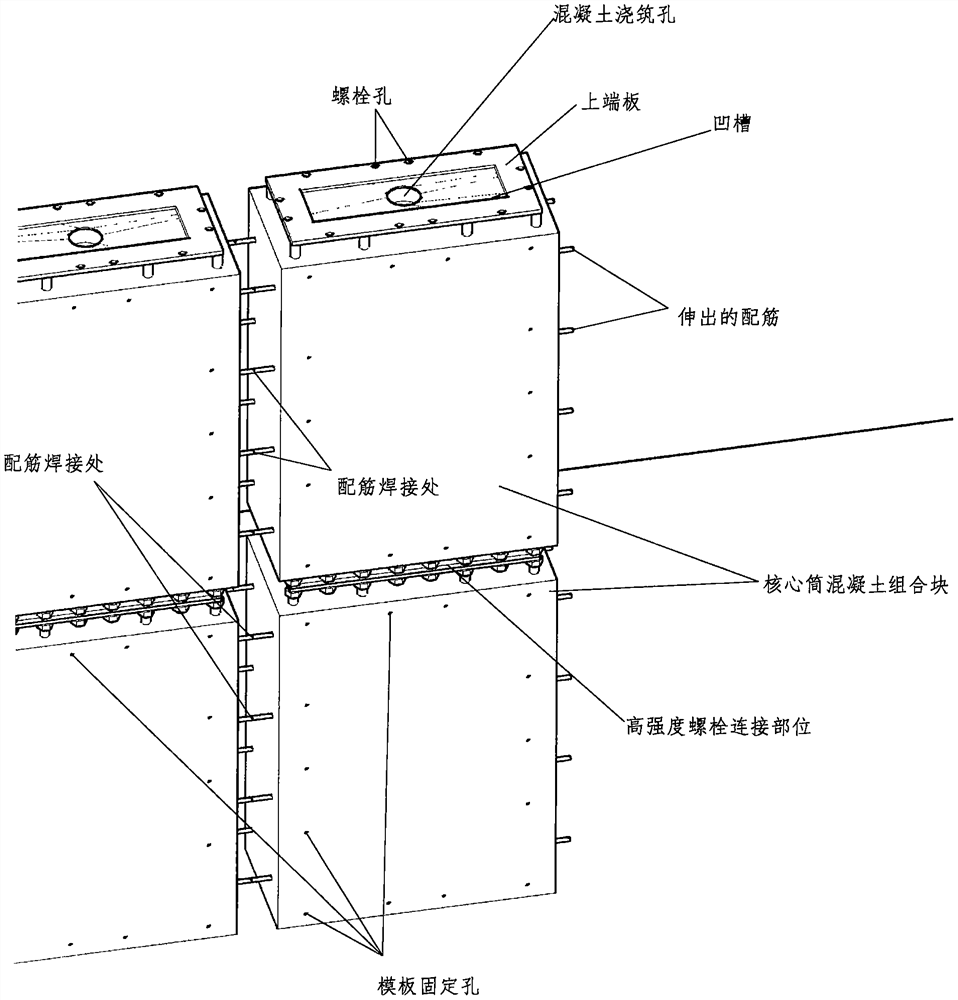
[0023] 1. The upper and lower ends of the column are plates welded together with the reinforcement of the concrete in the column. There are through holes on the plate that can pass through high-strength bolts, and there is a large hole in the middle of the plate that can pass through the poured concrete. , There is a cavity formed by leaving a certain distance from the back of the plate to the end face of the concrete. In this cavity, bolts passing through the iron plate of the adjacent column can be installed to connect the two plates to each other as a whole.

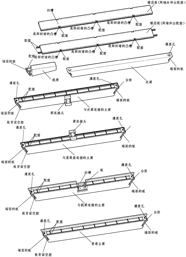
[0024] 2. The connection between the column and the beam is provided with a beam connector protruding from the column. The structure of the end of the connector is similar to that of the column: the end f...


PUM


Abstract

The invention relates to a method for implementing fabricated concrete house building by using a member with a novel connecting end, which is characterized in that stress member columns and beams (including a roof truss beam and a stair beam) for fabricated construction have the following common characteristics: the end surfaces of the stress member columns and beams are plates integrally welded with reinforcing bars in the members, a plurality of holes are formed in the plates, and a certain distance is reserved between the plates and concrete on the back surfaces of the plates; therefore, the components can be conveniently connected through high-strength bolts. After the components are mutually connected, concrete can be conveniently poured at the connecting position, the connecting strength of the finished component nodes is not lower than or even higher than the strength of the nodes finished through the technology that the concrete is poured after steel bars are bundled on site, and the frame assembled on site actually becomes a whole. And on-site concrete pouring is only carried out at the joints, and the pouring amount is far smaller than that of traditional concrete construction. Aerated concrete wallboards are adopted in the maintenance system, and it is guaranteed that the building has good heat preservation, sound insulation and heat insulation functions. The method has the beneficial effects that the assembly rate of a concrete assembly type building is greatly improved; the investment of a concrete member factory is reduced; the supply distance of a concrete member factory is expanded; the on-site construction cost is reduced, and the house building quality is improved.

Description

[0001] Technical field [0002] The invention relates to a method of building a house using a prefabricated concrete system. [0003] technical background [0004] The current method of building a house with a prefabricated concrete system has the following deficiencies: [0005] 1. The design and production of components have not yet been standardized, so there are a large number of components; components include various large prefabricated components, not only the cost of mold making is high, resulting in high cost of prefabricated parts, but also the transportation of large prefabricated parts Larger vehicles and some special brackets are required, and the additional transportation costs further increase the cost of building the house; the production of large-scale and various prefabricated reinforced concrete components determines the large investment of the concrete prefabricated component processing plant, which further limits its ubiquity of use. The above reasons cons...

Claims


Application Information

Patent Timeline
IPC IPC(8): E04B1/41E04B1/58E04B1/19E04C2/04E04C2/30E04B1/88
CPCE04B1/4157E04B1/58E04B1/19E04B1/1903E04C2/049E04C2/30E04B1/88E04B2103/02
Inventor 沈宇轩沈舞源万平华
Owner 万平华
Why Eureka
Try Eureka