A lens appearance inspecting system
A visual inspection and lens technology, which is used in measuring devices, material analysis by optical means, instruments, etc., can solve the problems of rare lens inspection, low operation efficiency, visual fatigue, etc., to improve inspection efficiency and product quality. The effect of stability and labor saving
- Summary
- Abstract
- Description
- Claims
- Application Information
AI Technical Summary
Problems solved by technology
Method used
Image
Examples
Embodiment 1
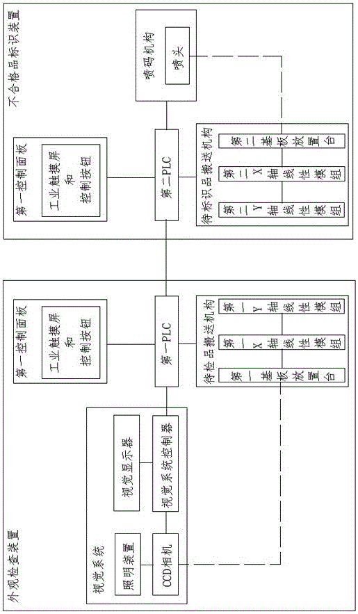
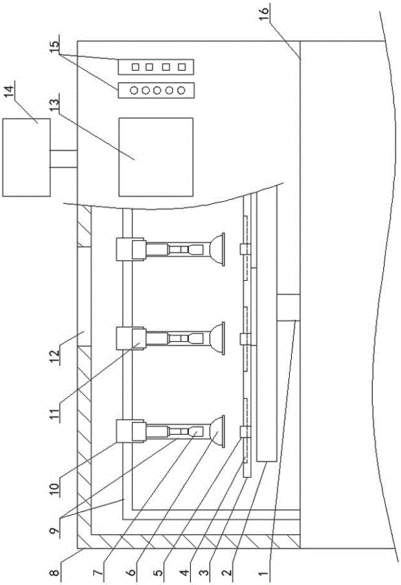
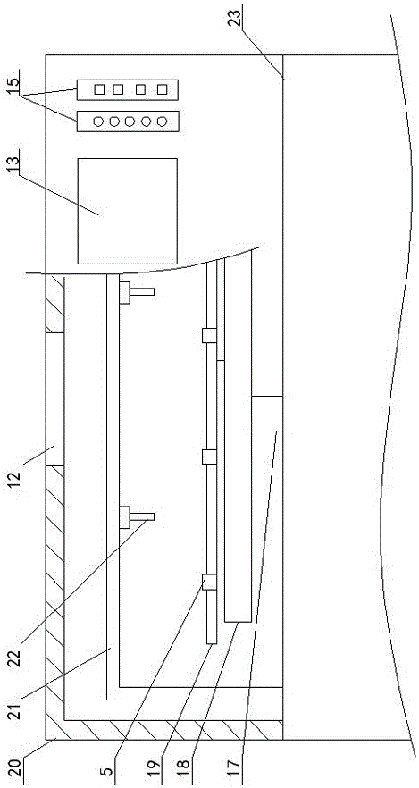
[0024] Embodiment 1, with reference to figure 1 —3. A lens visual inspection system, which includes:
[0025] Appearance inspection device, the device includes an inspection chassis 8, a vision system and a first PLC, the inspection chassis 8 is provided with a first control panel, the controller of the vision system and the first control panel are all connected to the first PLC, and the vision system includes a camera device, an operation platform 16 is provided in the inspection cabinet 8, and a support 9 is provided on the operation platform 16. The camera device is installed on the support 9 and placed above the walking mechanism of the product to be inspected. The walking mechanism of the product to be inspected is connected to the driving element , the walking drive element of the product to be inspected is connected with the first PLC; the machine vision system also includes a visual display 14, the camera device is connected to the input of the visual system controller...
Embodiment 2
[0028] Embodiment 2, in the lens appearance inspection system described in Embodiment 1, the tops of the inspection cabinet 8 and the identification cabinet 20 are provided with ventilation holes 12, and high-efficiency filters are installed in the ventilation holes 12.
Embodiment 3
[0029] Embodiment 3, in the lens appearance inspection system described in Embodiment 1, the first control panel and the second control panel both include an industrial touch screen 13 and control buttons 15, and the industrial touch screen 13 and the second control panel of the first control panel One PLC is connected by Ethernet communication mode, the control button 15 of the first control panel is electrically connected with the first PLC, the industrial touch screen 13 of the second control panel is connected with the second PLC by Ethernet communication mode, the control button of the second control panel 15 is electrically connected with the second PLC, and the control button 15 is used to switch the working mode, and the control button 15 includes emergency stop, start, stop, reset, disk withdrawal and lens selection buttons.
PUM
 Abstract
Description
Claims
Application Information
 - R&D
- Intellectual Property
- Life Sciences
- Materials
- Tech Scout
- Unparalleled Data Quality
- Higher Quality Content
- 60% Fewer Hallucinations
Browse by: Latest US Patents, China's latest patents, Technical Efficacy Thesaurus, Application Domain, Technology Topic, Popular Technical Reports.
© 2025 PatSnap. All rights reserved.Legal|Privacy policy|Modern Slavery Act Transparency Statement|Sitemap|About US| Contact US: help@patsnap.com


