Dynamic automatic shimming method for magnetic resonance imaging

A magnetic resonance imaging and automatic shimming technology, which is applied in the direction of measuring magnetic variables, measuring devices, instruments, etc., can solve the problem of long time for shimming methods, and achieve the effect of reducing shimming time, reducing time, and reducing time

Active Publication Date: 2016-12-21
INST OF ELECTRICAL ENG CHINESE ACAD OF SCI
View PDF5 Cites 11 Cited by
  • Summary
  • Abstract
  • Description
  • Claims
  • Application Information

AI Technical Summary

Problems solved by technology

[0011] The purpose of the present invention is to propose a new fast dynamic automatic shimming method in order to solve the time-consuming problem of the existing shimming method

Method used


Image

  • Dynamic automatic shimming method for magnetic resonance imaging
  • Dynamic automatic shimming method for magnetic resonance imaging
  • Dynamic automatic shimming method for magnetic resonance imaging

Examples


Embodiment Construction

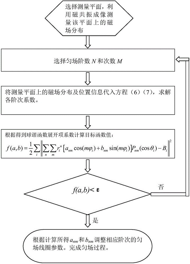
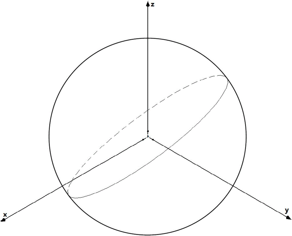
[0036] like figure 1 As shown, in the embodiment of the present invention, the measurement plane is imaged twice using a magnetic resonance imaging sequence. The echo time difference between the two imagings is 1 millisecond, and the measurement plane passes through the zero point of the gradient. The rotation angles are 40°, 20°, 35°. In view of the sensitivity of the gradient echo to the change of the magnetic field, this implementation adopts the gradient echo imaging sequence to perform two magnetic resonance imaging on the plane, and the echo time of the two imaging is 20 milliseconds and 21 milliseconds respectively. After collecting the two imaging data, calculate the phase difference of the two imaging data, in order to avoid the phase warping error, the complex number division is used for operation, namely:

[0037]

[0038] In the formula, i represents the serial number of the image data point, Indicates the phase difference between the two measured imaging data,...


PUM


Abstract

The invention discloses a dynamic automatic shimming method for magnetic resonance imaging. Magnetic field distribution on any one plane of an imaging area is measured by use of the magnetic resonance imaging, and an object function is established on the measurement plane. The object function is described as follows: any one group of coefficients anm and bnm are searched so that a deviation quadratic sum between a magnetic field spheric harmonics function expanded formula on the measurement plane and the measured magnetic field distribution is enabled to be smallest. First-order partial derivatives of the coefficients anm and bnm are solved through the object function so that the object function obtains a minimum value when each first-order partial derivative is zero. Equations when each first-order partial derivative is zero are simultaneously established, and the various coefficient anm and bnm of the magnetic field spheric harmonics function expanded formula in the imaging area are calculated. The coefficients anm and bnm are substituted into the object function for calculating a deviation quadratic sum, according to a deviation, whether a shimming order needs to be adjusted and whether calculation of a next time is carried out are determined. Finally, according to the coefficients anm and bnm of each order, shimming coil parameters of the corresponding order are adjusted, and thus a shimming process is completed.

Description

technical field [0001] The invention relates to a method for leveling a magnetic field, in particular to a method for dynamically leveling a main magnetic field for magnetic resonance imaging. Background technique [0002] The main magnetic field required for magnetic resonance imaging should not only maintain stability and achieve sufficient field strength, but also ensure sufficient uniformity. The uniformity of the main magnetic field is a very important indicator of the magnetic resonance imaging system. Magnetic field uniformity largely determines the quality of MRI images, such as image signal-to-noise ratio (SNR), spatial resolution (SR), and geometric distortion of the effective field of view (FOV). The magnetic field uniformity of the main magnet can be quantitatively described by the following definition: [0003] Δ B B 0 × 10 6 ...

Claims


Application Information

Patent Timeline
Patent Type & Authority Applications(China)
IPC IPC(8): G01R33/3875
CPCG01R33/3875
Inventor 王慧贤杨文晖王铮魏树峰
Owner INST OF ELECTRICAL ENG CHINESE ACAD OF SCI
Why Eureka
Try Eureka