
Light guide plate capable of eliminating hot spot phenomenon and backlight module thereof

A technology of backlight module and light guide plate, applied in the field of light guide plate, can solve the problem of hot spot phenomenon of the light guide plate, and achieve the effect of increasing the light emission angle, the effect of real and effective dimming, and the effect of eliminating uneven brightness and darkness.

Inactive Publication Date: 2016-12-21
SHANGHAI XIANGLONG ELECTRONICS TECH
View PDF8 Cites 7 Cited by
  • Summary
  • Abstract
  • Description
  • Claims
  • Application Information

AI Technical Summary

Problems solved by technology

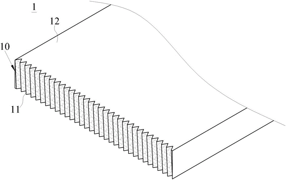
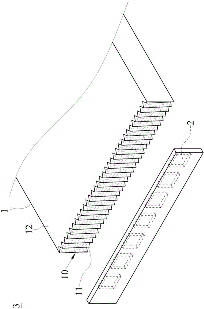
[0005] The technical problem to be solved by the present invention is to overcome the defect that the hot spot phenomenon will be formed near the light source in the light guide plate in the prior art, and provide a light guide plate and its backlight module that can eliminate the hot spot phenomenon. The structural design can effectively eliminate the phenomenon of uneven brightness and darkness, and improve the optical characteristics of the light guide plate

Method used


Image

  • Light guide plate capable of eliminating hot spot phenomenon and backlight module thereof
  • Light guide plate capable of eliminating hot spot phenomenon and backlight module thereof
  • Light guide plate capable of eliminating hot spot phenomenon and backlight module thereof

Examples


Embodiment Construction

[0040] The present invention is further illustrated below by means of examples, but the present invention is not limited to the scope of the examples.

[0041] Light has extremely sensitive physical characteristics, and a slight structural change may cause the divergence angle to be completely opposite to the expected result. Therefore, many structural details must be paid attention to when designing the light guide plate. In the initial stage of developing the light guide plate, in order to know the effect of the light-spreading microstructure and the rough surface on the light-incident side surface on the incident light angle, the inventors used four groups of different light guide plates for experimental comparison. The side surface does not have a light-spreading microstructure and is a light guide plate with a polished mirror surface; the second group is a light-guide plate that does not have a light-spreading tooth on the light-incident side surface but is a rough matte s...


PUM


Abstract

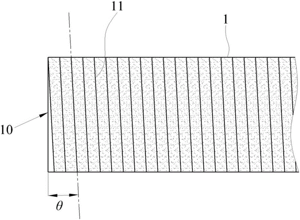
The invention provides a light guide plate capable of eliminating hot spots and its backlight module. The light guide plate has a light incident surface and a number of spreading teeth. The light incident surface is used to receive light from at least one light source. The light incident surface, and the point light source corresponds to at least any three adjacent spreader teeth, so that the projected area of ​​the point light source on the light incident surface covers the aforementioned at least three adjacent spreader teeth. The surface roughness of each spreader tooth is greater than 0.9 μm, and the light from the point light source is first projected onto at least three adjacent spreader teeth, scattered through the spreader tooth structure, and at the same time passed through its surface roughness greater than 0.9 μm Diffuse due to the structure, thereby increasing the luminous angle of the light entering the light incident surface, thereby eliminating the hot spot phenomenon and improving the optical characteristics.

Description

technical field [0001] The invention relates to the field of light guide plates, in particular to a light guide plate capable of eliminating hot spots and a backlight module thereof. Background technique [0002] The light guide plate is an optical component used to guide light to form a surface light source, and is widely used in devices such as backlight modules or lamps. Taking the backlight module as an example, it can be divided into direct type and side type according to the relative position of the light source and the light guide plate. Thick direct-type backlight modules are gradually being replaced by edge-type backlight modules. In the side-lit backlight module, light-emitting diodes (hereinafter referred to as LEDs) as light sources are generally arranged at intervals on the side of the light guide plate, so that the light of each LED enters the interior from a light-incident side of the light guide plate, and is formed on the light guide plate. The surface lig...

Claims


Application Information

Patent Timeline
IPC IPC(8): G02B6/00F21V8/00G02F1/13357
CPCG02B6/0038G02F1/1336
Inventor 鲁浩李文妤
Owner SHANGHAI XIANGLONG ELECTRONICS TECH
Learn More