Light guide panel of edge-light type backlight system and edge-light type backlight system employing the same

a backlight system and light guide panel technology, applied in the field of backlight systems, can solve the problems of narrow operating temperature range, uneven brightness of the screen of an fpd illuminated by the backlight system, etc., and achieve the effect of improving the luminance of the light guide panel

Active Publication Date: 2007-05-29
SAMSUNG DISPLAY CO LTD
View PDF20 Cites 61 Cited by
  • Summary
  • Abstract
  • Description
  • Claims
  • Application Information

AI Technical Summary

Benefits of technology

[0013]The present invention provides a light guide panel and an edge-light type backlight system employing the same, in which an angle of light introduced into the light guide panel is widened to remove dark areas between point light sources, and then reduced again to improve luminance of the light guide panel.

Problems solved by technology

However, CCFLs have disadvantages as well, such as being operated by a high-frequency AC signal and has a narrow operating temperature range.
When there are dark areas, a screen of an FPD illuminated by the backlight system suffers unevenness in brightness across the areas.

Method used


Image

  • Light guide panel of edge-light type backlight system and edge-light type backlight system employing the same
  • Light guide panel of edge-light type backlight system and edge-light type backlight system employing the same
  • Light guide panel of edge-light type backlight system and edge-light type backlight system employing the same

Examples


Embodiment Construction

[0030]The present invention will now be described more fully with reference to the accompanying drawings, in which exemplary embodiments of the invention are shown.

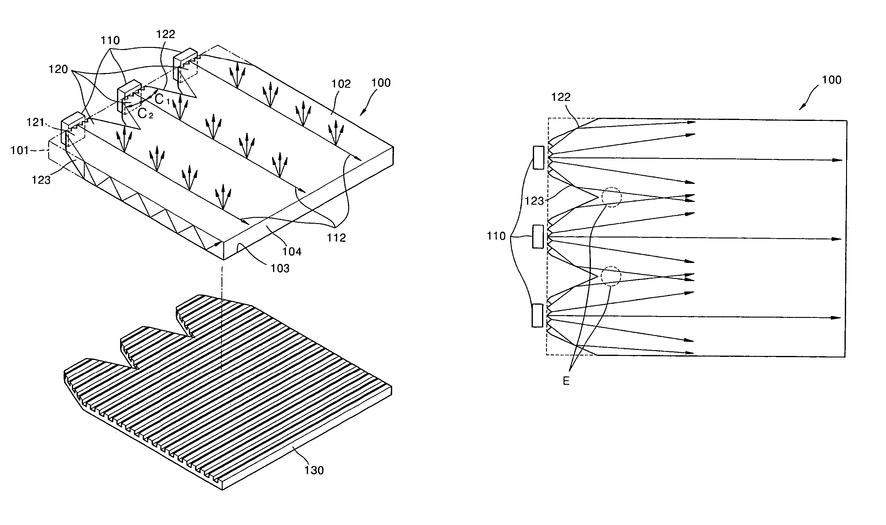
[0031]FIG. 4 is a perspective view of an edge-light type backlight system according to an exemplary embodiment of the present invention, and

[0032]FIG. 5 is an enlarged perspective view of a light incident part 120 of the edge-light type backlight system of FIG. 4.

[0033]Referring to FIGS. 4 and 5, a light guide panel 100 has a flat panel shape. Three light emitting diodes (LED) 110 are arranged along a virtual edge surface 101 of the light guide panel 100. An optical path-changing unit 130 is disposed under the light guide panel 100.

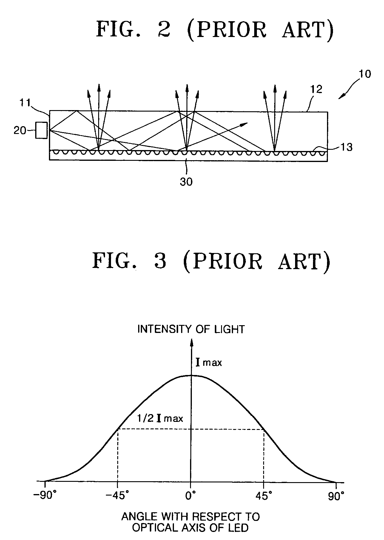
[0034]Each of the LEDs 110 acting as a point light source emits light within a spread of ±90 degrees about an optical axis 112. Here, as shown in FIG. 3, an angle at which light emitted from an LED has a half-maximum intensity is about 45 degrees.

[0035]The light guide panel 100 is made of a tra...


PUM

PropertyMeasurementUnit
apex angleaaaaaaaaaa
refractive indexaaaaaaaaaa

Abstract

An edge-light type backlight system including a point light source, a light guide panel including a light incident part into which light enters from the point light source and a light emitting surface from which light is emitted, and an optical path-changing unit which changes a propagation path of light traveling inside the light guide panel. The light incident part includes a light incident surface on which a prism pattern is formed, the light incident surface facing the point light source, and first and second surfaces extending from the light incident surface in a direction in which light travels inside the light guide panel and adapted to reflect light passing through the light incident surface to reduce a direction angle, the first and second surfaces being opposite to each other with respect to an optical axis.

Description

BACKGROUND OF THE INVENTION[0001]This application claims priority from Korean Patent Application No. 2003-23978, filed on Apr. 16, 2003, with the Korean Intellectual Property Office, the disclosure of which is incorporated herein in its entirety by reference.[0002]1. Field of the Invention[0003]The present invention relates to a backlight system, and more particularly to an edge-light type backlight system using a light guide panel and a point light source.[0004]2. Description of the Related Art[0005]Backlight systems are used in flat panel displays (FPDs), such as liquid crystal displays (LCDs) to ensure proper luminance or brightness. Backlight systems are classified according to arrangement of light sources as direct-light type backlight units in which a plurality of lamps installed under FPD directly emit light to a liquid crystal panel, and edge-light type backlight units in which a lamp installed along one edge side of a light guide panel emits light to a liquid crystal panel....

Claims


Application Information

Patent Timeline
Patent Type & Authority Patents(United States)
IPC IPC(8): F21V7/04F21V8/00F21Y101/00G02B6/00G02F1/13357
CPCG02B6/0016G02B6/0018G02B6/0053G02F1/1335
Inventor MIN, JEE-HONGCHOI, HWAN-YOUNGLEE, MOON-GYUKIM, JIN-HWANCHOI, JIN-SEUNG
Owner SAMSUNG DISPLAY CO LTD
Why Eureka
Try Eureka