Surface light source unit, surface illumination device, and liquid crystal display device

a surface light source and illumination device technology, applied in the field of surface light source units, surface illumination devices, and liquid crystal display devices, can solve the problems of reducing the light intensity of the edge-light type backlight, requiring an expensive light guide plate, and a large amount of attenuation of light, so as to reduce the thickness and reduce the thickness

Active Publication Date: 2012-10-25
OPTO DESIGN INC
View PDF2 Cites 56 Cited by
  • Summary
  • Abstract
  • Description
  • Claims
  • Application Information

AI Technical Summary

Benefits of technology

[0078]In the liquid crystal display device of the present invention, a surface illumination device of a direct type using a point light source has

Problems solved by technology

The edge-light type backlight requires an expensive light guide plate.
Thus, to obtain a large light emitting surface, a large light guide plate is required which leads to a heavier weight and a higher cost.
Furthermore, when such a large light guide plate is used, the light path between the light source and a light emitting surface is long and thus, light is largely attenuated.
Therefor

Method used


Image

  • Surface light source unit, surface illumination device, and liquid crystal display device
  • Surface light source unit, surface illumination device, and liquid crystal display device
  • Surface light source unit, surface illumination device, and liquid crystal display device

Examples


first embodiment

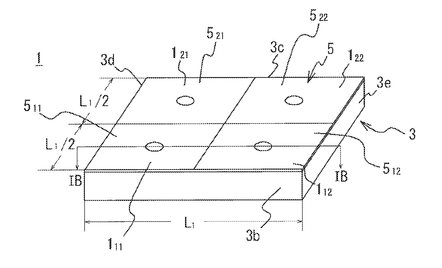
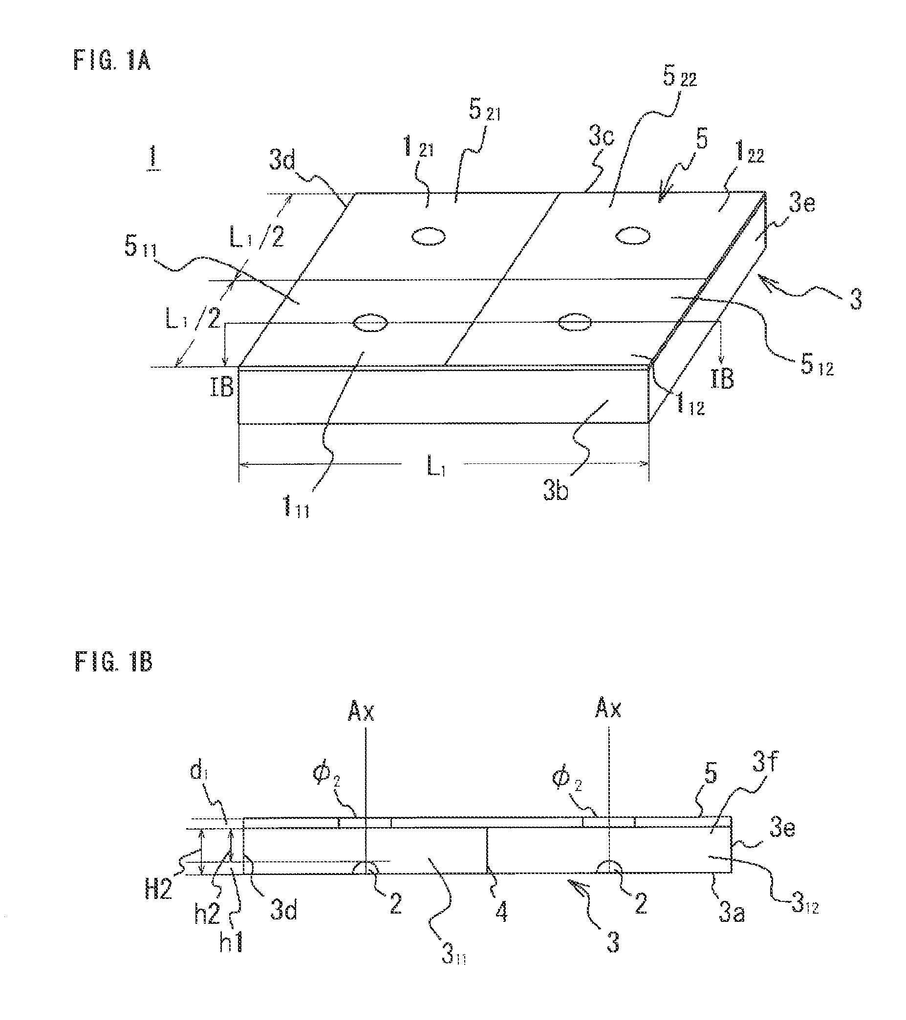
[0106]A surface light source unit according to a first embodiment of the present invention will be described with reference to FIG. 1 to FIG. 5. FIG. 1 illustrates the surface light source unit according to the first embodiment of the present invention. FIG. 1A is a schematic diagram of the surface light source unit. FIG. 1B is a cross-sectional view taken along the line IB-IB in FIG. 1A. FIG. 2 is a perspective view of one of the cell light sources in the surface light source unit in FIG. 1. FIG. 3 is an exploded perspective view of the cell light source in FIG. 2. FIG. 4 is a cross-sectional view of the cell light source taken along the line IV-IV in FIG. 2. FIG. 5A is a diagram illustrating an opening ratio curve of an opening provided in a light transmitting / reflecting plate in FIG. 2. FIG. 5B is an enlarged view of openings provided in the light transmitting / reflecting plate.

[0107]First of all, a surface light source unit 1 of the first embodiment of the present invention is de...

second embodiment

[0135]A surface light source unit 1A according to a second embodiment of the present invention will be described with reference to FIG. 6 and FIG. 7, FIG. 6 illustrates the surface light source unit according to the second embodiment of the present invention. FIG. 6A is a schematic diagram of the surface light source unit. FIG. 6B is a cross-sectional view taken along the line VIB-VIB in FIG. 6A. FIG. 7 is a perspective view of one of the cell, light sources in the surface light source unit in FIG. 6.

[0136]A surface light source unit 1A according to the second embodiment of the present invention is formed by dividing the surface light source unit 30 (see FIG. 26) of the conventional technique into 16 small cell light sources 1A11 to 1A44. The small cell light sources 1A11 to 1A44 have substantially the same configuration and are similar in shape to the surface light source unit 30 of the conventional technique. In the description given below, the portions same as those of the conven...

third embodiment

[0151]A surface light source unit 15 according to a third embodiment of the present invention will be described with reference to FIG. 10. FIG. 10 is an exploded perspective view of the surface illumination device according to the third embodiment of the present invention. In the surface light source unit 1B according to a third embodiment of the present invention, some of the partition plates 4 in the surface light source unit 1A according to the second embodiment are omitted. In the description given below, the portions same as those of the surface light source unit 1A according to the second embodiment are denoted with the same reference numerals, and the overlapping description will be omitted. Different portions will be described in detail.

[0152]The surface light source unit 1B includes 12 LEDs 2, a housing 35 in which the LEDs are disposed, and a light transmitting / reflecting plate 5B that covers the opening of the housing. The housing 3B has an internal space partitioned into...


PUM


Abstract

Provided is a surface light source unit which has a high-directivity point light source and has a decreased thickness in the in the direction in which light is irradiated from said point light source. Also provided are a surface illumination device and a liquid crystal display device. A plurality of small chambers (311 to 322) having an opening on the top are formed in a housing (3) from side plates (3b to 3e) that have a predetermined height and partition plates (4) which partition the inside of the housing (3). Each small chamber is provided with a point light source (2) on the bottom part. The opening of each small chamber (311 to 322) is covered with a light transmitting/reflecting plate (511 to 522) which has a surface area (S), and comprises: a central reflecting section that has a surface area (ΔS), exhibits high reflectance and low transmittance, and is positioned directly above the point light source (2); and an outer reflecting section that surrounds the central reflecting section and is configured so that the light transmittance increases at distances further from the central reflecting section. The surface area (ΔS) and surface area (S) of each light transmitting/reflecting plate (511 to 522) are set in a manner such that the ratio ΔS/S is a predetermined value.

Description

TECHNICAL FIELD[0001]The present invention relates to a surface light source unit, a surface illumination device, and a liquid crystal display device. It particularly relates to a surface light source unit that includes a point light source that has high directivity, converts point light from the point light source into surface light of a predetermined area, and radiates the surface light, and to a surface illumination device and a liquid crystal display device that include the surface light source unit.BACKGROUND ART[0002]Recently, studies and developments on light emitting diodes (hereinafter referred to as “LEDs”) have rapidly advanced, and various types of LEDs have been developed and commercialized to be used in a wide range of fields, while the use of LEDs in the field of lighting is becoming increasingly popular. In the field of lighting, LEDs are used not only as a substitute for fluorescent lights and light bulbs but also for, for example, backlights for liquid crystal disp...

Claims


Application Information

Patent Timeline
IPC IPC(8): F21V13/02G02F1/13357F21V13/12
CPCG02F1/133603G02F1/133605G02F1/133611H01L25/0753H01L33/60G02F1/133608H01L2924/0002F21V11/12F21V11/14G02F1/133606H01L2924/00
Inventor SATO, EIICHISATO, HIROYASUSATO, KEN
Owner OPTO DESIGN INC
Why Eureka
Try Eureka