
Lighting system with color adjustment means

a technology of color adjustment and light source, which is applied in the direction of fixed installation, light source, lighting and heating apparatus, etc., can solve the problem of limited visible color spectrum of light produced by point light sources

Inactive Publication Date: 2010-02-23
ILIGHT TECH INC
View PDF13 Cites 62 Cited by
  • Summary
  • Abstract
  • Description
  • Claims
  • Application Information

AI Technical Summary

Benefits of technology

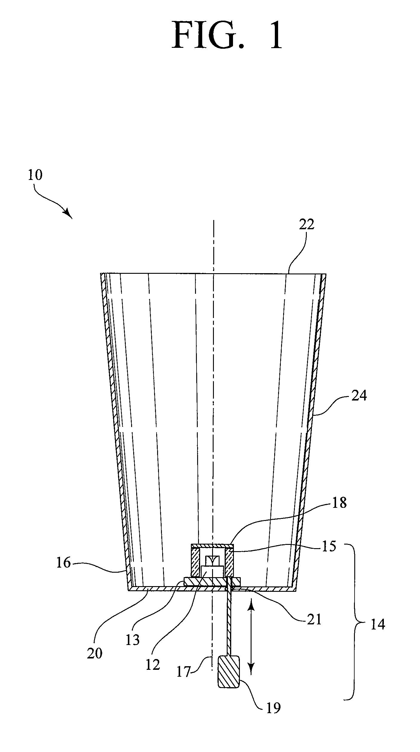
[0003]The present invention is a lighting system with a color adjustment means in which a desired hue can be achieved and finely tuned through use of the color adjustment means.
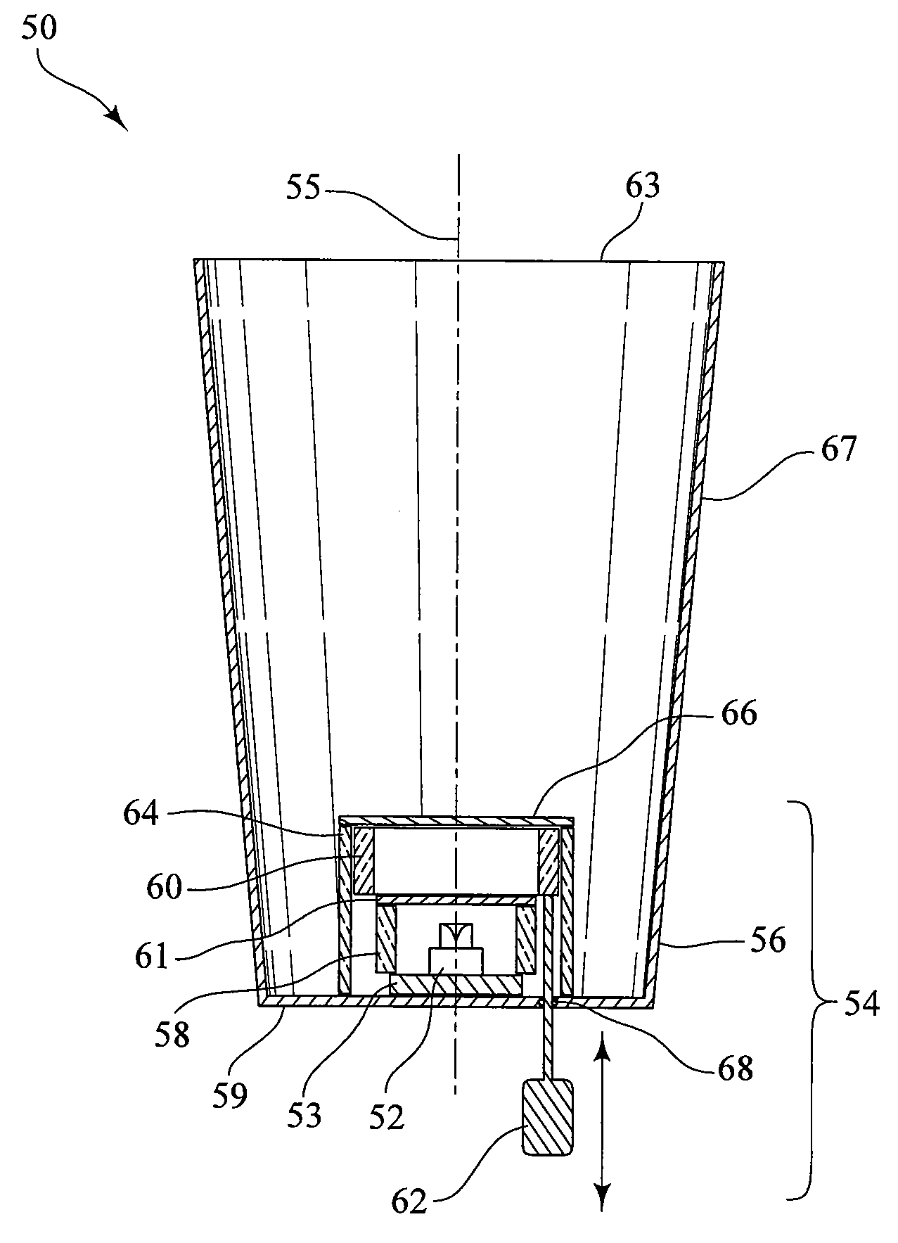
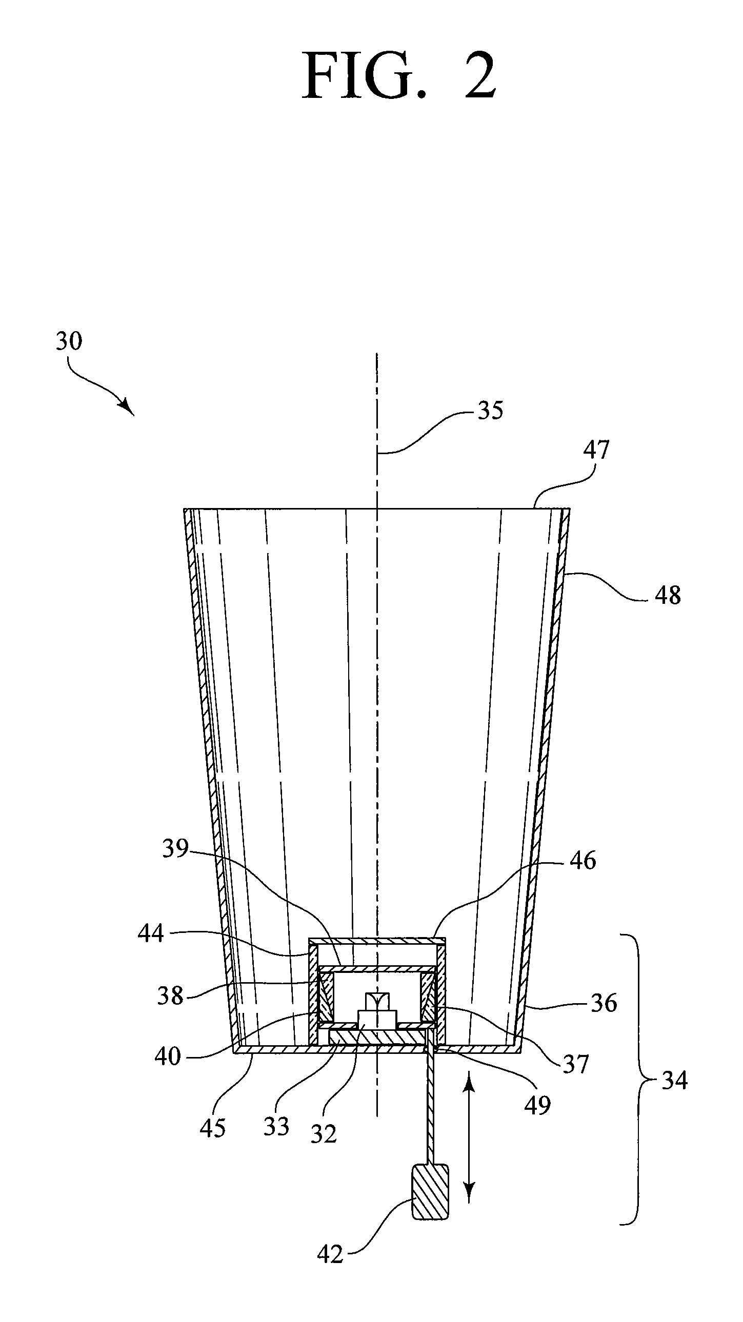
[0007]Generally described, in this second embodiment, the color adjustment means of the lighting system also includes a retaining ring having an end proximate the base. The retaining ring is made of a light-transmitting material, is axially aligned with the point light source, and further houses the tubular structure for guiding the tubular structure as it is moved towards or away from the base. The retaining ring may be clear, or it may be frosted to aid in the mixing of the light.
[0008]Furthermore, in this second embodiment, the lighting system can include a retaining ring cover connected to a distal end of the retaining ring for limiting a travel of the tubular structure.
[0012]In yet another variation of the second embodiment, the tubular structure can include a color-converting ring formed of a plurality of light-transmitting rods arranged side-by-side to form the tubular structure and a reflector disk connected to an end of the color-converting ring distal from the base. At least one of the rods can be of a first length, at least one of the rods can be of a second length, and at least one of the rods can be of a third length, such that the rods can be in a staggered arrangement so that a portion of the light from the point light source can escape without passing through the color adjustment means.

Problems solved by technology

However, a problem with many point light sources is that the available visible color spectrum of light produced by the point light sources is limited.

Method used


Image

  • Lighting system with color adjustment means
  • Lighting system with color adjustment means
  • Lighting system with color adjustment means

Examples


Embodiment Construction

[0029]The present invention is a lighting system with a color adjustment means in which a desired hue can be achieved and finely tuned through use of the color adjustment means.

[0030]For purposes of the discussion that follows, it is important to recognize that most perceived “colors” are not representative of light of a single wavelength, but rather some combination of wavelengths. In this regard, the dominant or perceived color of light comprised of some combination of wavelengths is generally referred to as hue. In order to provide a mechanism to represent and identify all possible perceived colors, the Commission Internationale l'Eclairage (CIE) constructed the CIE Chromaticity Diagram, which is based on three ideal primary light colors of red, blue, and green. The CIE Chromaticity Diagram is a well-known tool for identifying colors and is well understood by one of ordinary skill in the art. Specifically, since the x-axis of this CIE Chromaticity Diagram represents the amount of...


PUM


Abstract

A lighting system include a point light source, a tubular color adjustment means, and a light-collecting and mixing element. The color adjustment means has a color-converting tubular structure and an adjusting rod. The tubular structure is made of a light-transmitting medium doped with a wavelength-converting material. The adjusting rod is operably connected to and for adjusting the tubular structure. In operation, the point light source emits light of a first wavelength or hue. The color adjustment means adjustably intersects, through the use of the adjusting rod, the light of the first hue and converts at least a portion of the light of a first hue into a light of another hue. The light-collecting and mixing element collects and mixes the light of a first hue and the light of another hue, and directs the mixed light out the open end.

Description

CROSS-REFERENCE TO RELATED APPLICATIONS[0001]This application claims priority to U.S. Provisional Patent Application No. 60 / 821,047, filed Aug. 1, 2006, the entire disclosure of which is incorporated herein by reference.BACKGROUND OF THE INVENTION[0002]It is desirable to adjust the color of lighting systems utilizing point light sources, including light-emitting diodes (LEDs), metal halide light sources, and ultraviolet light sources, for general and task illumination on a widespread basis. However, a problem with many point light sources is that the available visible color spectrum of light produced by the point light sources is limited. For instance, LEDs are available only in limited colors. Therefore, in commonly assigned U.S. Pat. No. 7,011,421, and in commonly assigned and co-pending U.S. patent application Ser. No. 11 / 025,019, each of which is incorporated in its entirety herein by this reference, illumination devices are described that use fluorescent and / or phosphorescent d...

Claims


Application Information

Patent Timeline
IPC IPC(8): F21S8/00
CPCF21K9/00F21V9/10F21V9/16F21K9/58F21V14/08F21K9/56F21Y2101/02F21K9/64F21K9/65F21V9/32F21V9/38F21V9/45F21V13/14F21Y2115/10
Inventor HULSE, GEORGE R.WILKIEL, LLOYD S.
Owner ILIGHT TECH INC
Learn More