Surface light source device and liquid crystal display device

a liquid crystal display and light source technology, applied in the direction of lighting and heating equipment, planar/plate-like light guides, instruments, etc., can solve the problems of reducing the height of light sources including leds, affecting the efficiency of light use, and partially leakage of light to the outsid

Active Publication Date: 2013-09-19
TOHOKU DENSHI CO LTD
View PDF2 Cites 60 Cited by
  • Summary
  • Abstract
  • Description
  • Claims
  • Application Information

AI Technical Summary

Benefits of technology

[0010]At least one embodiment of the present invention has been made in view of the above technical problems, and an object thereof is to prevent light from leaking from a side surface o...

Problems solved by technology

However, even if the flat light guide plate can be reduced in thickness, there is a limitation to reducing a height of a light source including an LED.
When the light source projects above from the light guide plate, light emitted from the light source is not entirely inciden...

Method used


Image

  • Surface light source device and liquid crystal display device
  • Surface light source device and liquid crystal display device
  • Surface light source device and liquid crystal display device

Examples


first embodiment

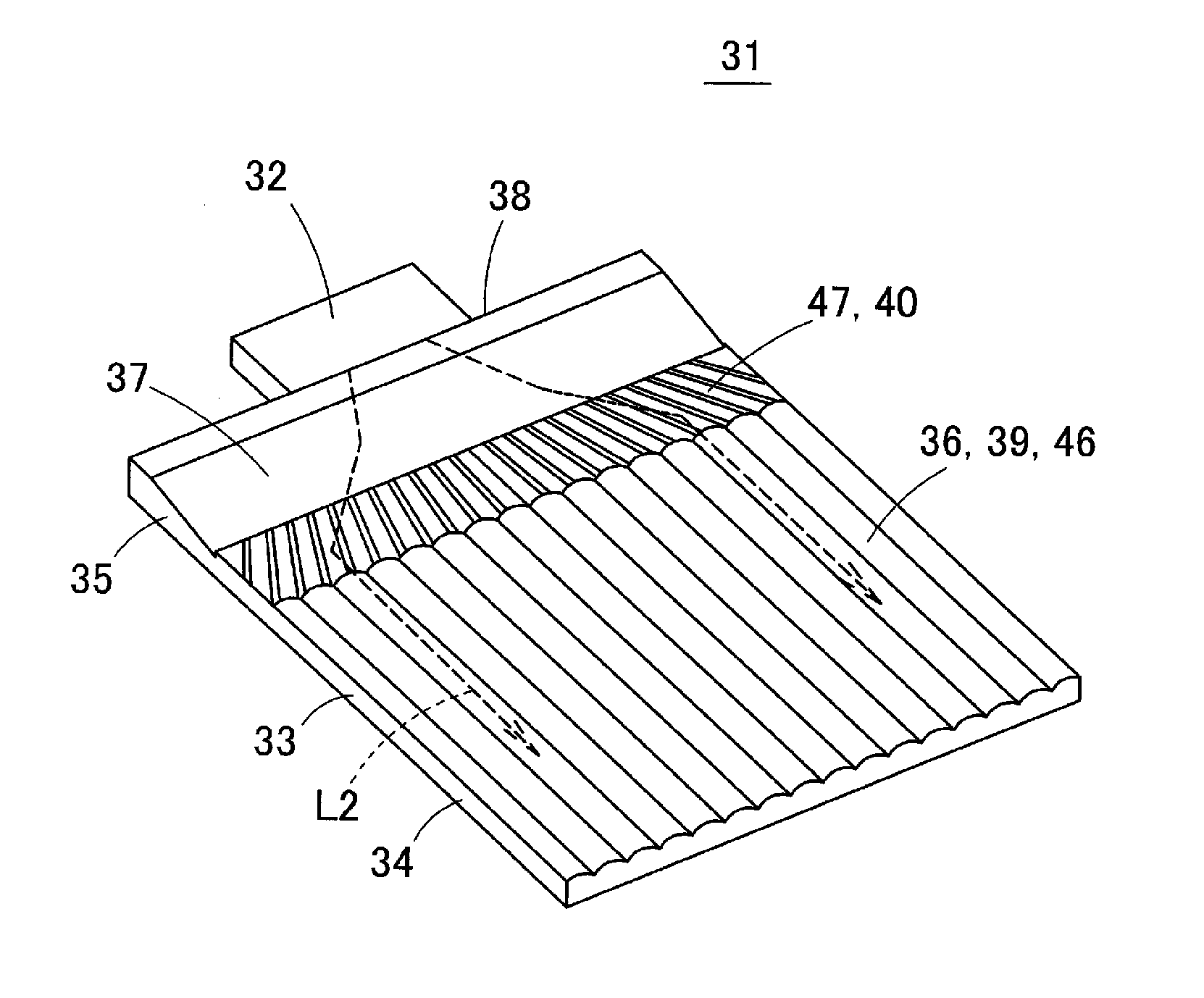
[0069]A surface light source device 31 according to a first embodiment of the present invention will be described below with reference to FIGS. 3 to 7B. FIG. 3 is a perspective view illustrating the surface light source device 31 of the first embodiment, and FIG. 4A is a plan view of the surface light source device 31. FIG. 4B is a sectional view taken along line X-X in FIG. 4A, and illustrates a section of a lenticular lens 36 provided in a surface of a light guide plate 33. FIG. 5 is a schematic sectional view along a longitudinal direction (a direction perpendicular to a light incident surface 38) of the surface light source device 31, and illustrates a behavior of a ray in the light guide plate 33. FIG. 6 is a view illustrating a section of a directivity conversion pattern 40 in a section parallel to the light incident surface 38 of the light guide plate 33, and also illustrates a part of the directivity conversion pattern 40 in an enlarged form. FIGS. 7A and 7B illustrate behav...

second embodiment

[0103]FIG. 19 is a perspective view illustrating a surface light source device 61 according to a second embodiment of the present invention. FIG. 20 is a plan view of the surface light source device 61. FIG. 21 illustrates a cross sectional shape of the directivity conversion pattern 40 in the cross section parallel to the light incident surface 38. FIG. 21 also illustrates a part of the directivity conversion pattern 40 in an enlarged form.

[0104]In the surface light source device 61 of the second embodiment, the directivity conversion pattern 40 is partially removed to form a flat surface 62 in proximity to the optical axis C of the point light source 32. Particularly, in the example in FIGS. 19 and 20, the triangular flat surface 62 is provided so as to be sandwiched between the right and left directivity conversion patterns 40.

[0105]According to the structure of the second embodiment, the leakage of the light from the side surface of the light guide plate 33 or the lenticular len...

third embodiment

[0107]FIG. 23 is a perspective view illustrating a surface light source device 71 according to a third embodiment of the present invention. FIG. 24A is a plan view of the surface light source device 71. FIG. 24B is a sectional view taken along line Y-Y in FIG. 24A.

[0108]In the surface light source device 71 of the third embodiment, a light diffusion pattern 72, which laterally spreads the directivity of the reflected light, is formed in the upper surface and / or the lower surface of the light introduction part 35. As illustrated in FIG. 24B, the light diffusion pattern 72 may be formed by arranging vertically extending V-grooves 72a in parallel with one another, or the light diffusion pattern 72 may be a pattern having a lenticular-lens shape or a random shape. In the structure of the third embodiment, the light is sent to the side surface direction of the light guide plate 33 while being laterally spread by the light diffusion pattern 72, thereby preventing darkening of a side edge ...


PUM


Abstract

In a surface light source device, a light guide plate includes a light introduction part that traps the light emitted from a point light source and incident from a light incident surface, and a light guide plate body. The light introduction part includes an inclined surface inclined from a surface in a portion having a thickness larger than that of the light guide plate body toward an end of the surface of the light guide plate body. The light guide plate body includes a directivity conversion pattern located between an effective lighting region of the light guide plate body and the light introduction part. The directivity conversion pattern converts a directivity direction of the light from the light introduction part to the effective lighting region such that an angle formed by the directivity direction and a direction perpendicular to the light incident surface decreases when viewed from above.

Description

[0001]Priority is claimed under 35 U.S.C. §119 to Japanese Patent Application No, JP2012-059419 filed on Mar. 15, 2012, which is hereby incorporated by reference in its entirety,BACKGROUND OF THE INVENTION[0002]1. Technical Field[0003]The present invention relates to a surface light source device and a liquid crystal display device, and specifically to a surface light source device that is used as a backlight for a liquid crystal display, and a liquid crystal display device in which the surface light source device is used.[0004]2. Related Art[0005]Nowadays, there is an increasing demand for a low profile of a surface light source device with the progress of a low-profile mobile device provided with the surface light source device. In order to reduce a thickness of the surface light source device, it is necessary to reduce a thickness of a light guide plate. However, even if the flat light guide plate can be reduced in thickness, there is a limitation to reducing a height of a light ...

Claims


Application Information

Patent Timeline
IPC IPC(8): F21V8/00
CPCG02B6/0016G02B6/0038G02B6/002G02B6/0018
Inventor KURATA, GOUOSHINOHARA, MASAYUKI
Owner TOHOKU DENSHI CO LTD
Why Eureka
Try Eureka