
Touch screen and display device

A touch screen and touch technology, applied in the direction of instruments, electrical digital data processing, data processing input/output process, etc., can solve the problem of small node capacitance Cx, affecting the accuracy of touch sensing, etc., to increase the frontal area, The effect of improving the sensing sensitivity and improving the accuracy

Inactive Publication Date: 2016-12-21
BOE TECH GRP CO LTD +1
View PDF5 Cites 7 Cited by
  • Summary
  • Abstract
  • Description
  • Claims
  • Application Information

AI Technical Summary

Problems solved by technology

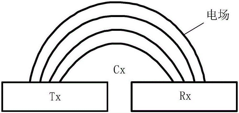
[0004] In order to solve the above problems, the present invention provides a touch screen and a display device, which at least partially solve the problem that the node capacitance Cx formed between the touch drive electrode Tx and the touch sensing electrode Rx of the existing touch screen is relatively small, so that the finger touches the screen. The change of capacitance Cx has little influence, thus affecting the accuracy of touch sensing

Method used


Image

  • Touch screen and display device
  • Touch screen and display device
  • Touch screen and display device

Examples


Embodiment 1

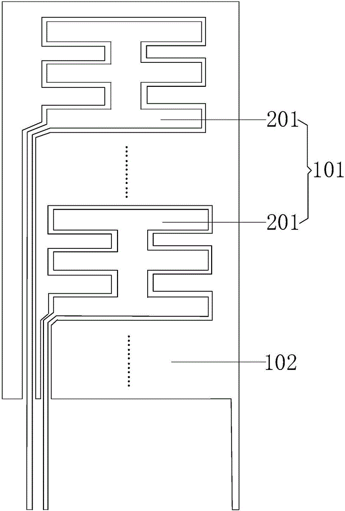
[0024] image 3 It is a schematic structural diagram of a touch screen provided by Embodiment 1 of the present invention. like image 3 As shown, the touch screen includes a plurality of first touch electrodes 101 and a plurality of second touch electrodes 102, the first touch electrodes 101 include a plurality of touch sub-electrodes 201, and the touch sub-electrodes 201 are set Within the second touch electrode 102, the touch sub-electrode 201 is arranged on the same layer as the second touch electrode 102, and the outer edge of the touch sub-electrode 201 is in contact with the second touch electrode. The inner edges of 102 are spaced a predetermined distance apart. In this embodiment, the touch sub-electrode 201 and the second touch electrode 102 are arranged on the same layer, which can ensure that the outer side of the touch sub-electrode 201 and the inner side of the second touch electrode 102 have a greater distance. of the facing area.

[0025] In this embodiment,...

Embodiment 2

[0034] This embodiment provides a display device, including the touch screen provided in the first embodiment, and the specific content can refer to the description of the first embodiment, which will not be repeated here.

[0035] In the display device provided in this embodiment, the touch screen includes a plurality of first touch electrodes and a plurality of second touch electrodes, the first touch electrodes include a plurality of touch sub-electrodes, and the touch sub-electrodes The electrodes are arranged in the second touch electrodes, the touch sub-electrodes are arranged in the same layer as the second touch electrodes, and the outer edges of the touch sub-electrodes and the inner edges of the second touch electrodes The edges are separated by a preset distance. The first touch electrode provided in this embodiment includes a plurality of touch sub-electrodes, the touch sub-electrodes are disposed inside the second touch electrodes, and the outer edges of the touch...


PUM


Abstract

The invention discloses a touch screen and a display device. The touch screen comprises multiple first touch electrodes and multiple second touch electrodes, wherein each first touch electrode comprises multiple touch sub-electrodes which are arranged in the second touch electrodes, the touch sub-electrodes and the second touch electrodes are arranged on the same layer, and outer edges of the touch sub-electrodes and the inner edges of the second touch electrodes are arranged at intervals of preset distance. Each first touch electrode comprises the multiple touch sub-electrodes which are arranged in the second touch electrodes, so that the directly facing area of the first touch electrodes and the second touch electrodes is increased. Therefore, higher node capacitance can be formed by the first touch electrodes and the second touch electrodes in the same region, the influence on change of the node capacitance is increased when a finger touches a screen, and the precision of touch induction is improved.

Description

technical field [0001] The invention relates to the field of display technology, in particular to a touch screen and a display device. Background technique [0002] With the rapid development of display technology, touch screen panels (Touch Screen Panels) have gradually spread into people's lives. At present, touch screens can be divided into: Add on Mode Touch Panel, On Cell Touch Panel and In Cell Touch Panel according to their structure. Among them, the plug-in touch screen is produced separately from the touch screen and Liquid Crystal Display (LCD), and then bonded to form a touch-enabled LCD screen. The plug-in touch screen has high production costs, low light transmittance, The module is thicker and other shortcomings. In the embedded touch screen, the touch electrodes are embedded in the liquid crystal display, which can not only reduce the overall thickness of the touch screen, but also reduce the production cost of the touch screen. [0003] figure 1 It is a s...

Claims


Application Information

Patent Timeline
Patent Type & Authority Applications(China)
IPC IPC(8): G06F3/041G06F3/044
CPCG06F3/0412G06F3/044G06F3/0443G06F3/0448G06F2203/04112
Inventor 邵贤杰崔显西
Owner BOE TECH GRP CO LTD
Learn More