
Sub-pixel boundary rapid detection method for cutter measurement

A detection method and sub-pixel technology, applied in the field of industrial vision, can solve problems such as complex calculation and difficulty in achieving real-time response, and achieve the effects of improving resolution, simple use and implementation, and improving accuracy

Inactive Publication Date: 2016-12-21
HUNAN UNIV
View PDF5 Cites 3 Cited by
  • Summary
  • Abstract
  • Description
  • Claims
  • Application Information

AI Technical Summary

Problems solved by technology

[0005] Aiming at the deficiency that the traditional boundary detection method can only achieve pixel-level precision, or the calculation is complicated, and it is difficult to achieve real-time response, the present invention proposes a fast boundary detection method with sub-pixel precision

Method used


Image

  • Sub-pixel boundary rapid detection method for cutter measurement
  • Sub-pixel boundary rapid detection method for cutter measurement
  • Sub-pixel boundary rapid detection method for cutter measurement

Examples


Embodiment Construction

[0029] The present invention will be further described below in conjunction with the accompanying drawings.

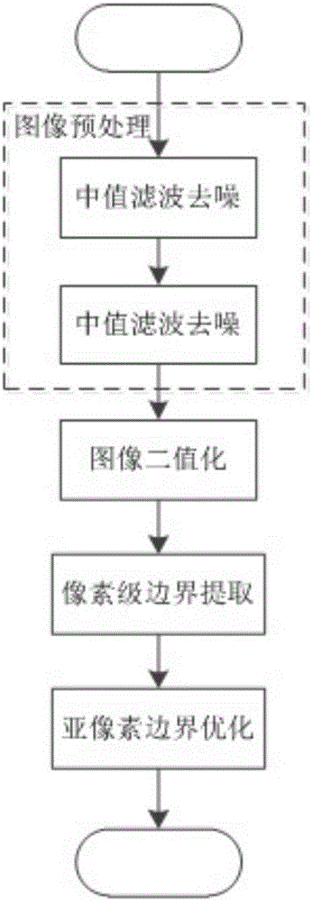
[0030] Such as image 3 As shown, the sub-pixel boundary detection method for tool measurement mainly includes four steps: image preprocessing, image binarization, pixel-level boundary extraction and sub-pixel boundary optimization.

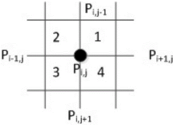
[0031] Input a picture of the tool to be measured, first use the median filter algorithm to filter out the salt and pepper noise in the image, and then use figure 1 The shown 5*5 discrete Log boundary enhancement operator template performs boundary enhancement on the image to be tested.

[0032] After the preprocessed picture, the threshold T of image binarization is dynamically determined based on the OTSU algorithm. If the gray value of the image is greater than T, it is 255, otherwise it is 0.

[0033] All boundaries in the image are clustered based on connectivity criteria. In order to eliminate the short boundary caused by noise...


PUM


Abstract

The invention discloses a sub-pixel boundary rapid detection method for tool measurement. The method includes four steps of image preprocessing, image binarization, pixel boundary location and sub-pixel boundary optimization. The image binarization adopts the OTSU method to automatically calculate the threshold of the image, so that the invention can adapt to the change of environmental brightness; based on the connectivity clustering, the pixel-level boundary of the image is obtained. In order to reduce the influence of noise, for the boundary whose length is less than the average boundary length Filtering out; sub-pixel boundary optimization adopts the method of bilinear interpolation, using the threshold value in the binarization method as a reference value, and interpolating in the x and y directions respectively to obtain the boundary of sub-pixel precision. Due to the adoption of the OTSU automatic threshold calculation method and bilinear interpolation method, the invention does not require manual interaction and parameter setting, and is simple in calculation, strong in robustness, and capable of adapting to changes in ambient brightness. Without increasing hardware costs, the invention can greatly Improve measurement accuracy in tool measurement.

Description

technical field [0001] The invention belongs to the field of industrial vision, and in particular relates to the measurement and detection of cutting tools. Background technique [0002] Modern CNC machine tools have high requirements on the accuracy of tool installation, especially in the field of precision machining, where the accuracy of tool parameter measurement directly affects the machining accuracy. On the other hand, in order to test the quality of products, tool manufacturers need to check whether each parameter of the tool meets the accuracy requirements of the design, and also need to measure the tool. [0003] At present, tool measurement is usually based on the principle of machine vision. Through optical imaging, the projection of the tool on the imaging plane is obtained, and various parameters of the tool are obtained by measuring the boundary of the image. However, some of the existing measurement methods are obtained by manually aligning the boundary of t...

Claims


Application Information

Patent Timeline
IPC IPC(8): G06T7/00G01B11/00
CPCG01B11/00G06T2207/20032
Inventor 谭光华朱贤益刘雪飞赵煜科蔡青宏
Owner HUNAN UNIV
Learn More