Novel gas discharge tube for coaxial cables
A technology of gas discharge tube and coaxial cable, which is applied in thermionic cathode tubes and other directions, can solve the problems of waste and loss, and achieve the effects of large lightning current capacity, excellent protection voltage, and reduced loss
- Summary
- Abstract
- Description
- Claims
- Application Information
AI Technical Summary
Problems solved by technology
Method used
Image
Examples
Embodiment 1
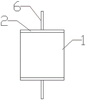
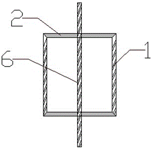
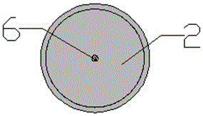
[0024] see Figure 1-4 , the present invention is a new type of gas discharge tube for coaxial cables, comprising a cylindrical cavity, the cavity is composed of a cavity wall 1 and plugs 2 at the upper and lower ends, and an inert gas is arranged in the cavity, wherein , the cavity is connected in series with the coaxial cable 4 by the metal shell 3, the two ends of the metal shell 3 are respectively connected to the coaxial cable 4 at both ends by the joint 5, and the electrode 6 is radially arranged in the cavity, and the two ends of the electrode 6 are respectively Through the upper and lower plugs 2, it is connected to the core 7 of the coaxial cable 4 at both ends; the cavity wall 1 is a conductor, and the metal shell 3 is connected to the grounding plate 8, and the cavity wall 1, the metal shell 3 and the grounding plate 8 are composed of The ground terminal; the upper and lower plugs 2 are insulating materials.
[0025] Wherein, the upper and lower plugs 2 are ceramic...
Embodiment 2
[0030] Such as Figure 5 As shown, a new type of gas discharge tube for coaxial cables includes a cylindrical cavity, the cavity is composed of a cavity wall 1 and plugs 2 at the upper and lower ends, and an inert gas is arranged in the cavity, wherein, The cavity is connected in series with the coaxial cable 4 by the metal shell 3, and the two ends of the metal shell 3 are respectively connected to the coaxial cable 4 at both ends by the joint 5, and an electrode 6 is arranged radially in the cavity, and the two ends of the electrode 6 respectively pass through The upper and lower plugs 2 are connected to the core 7 of the coaxial cable 4 at both ends; the cavity wall 1 is a conductor, and the metal shell 3 is connected to the grounding plate 8, and the cavity wall 1, the metal shell 3 and the grounding plate 8 form a ground connection end; the upper and lower plugs 2 are insulating materials.
[0031] Wherein, the upper and lower plugs 2 are ceramic insulating materials.
...
Embodiment 3
[0037] Such as Figure 5 As shown, a new type of gas discharge tube for coaxial cables includes a cylindrical cavity, the cavity is composed of a cavity wall 1 and plugs 2 at the upper and lower ends, and an inert gas is arranged in the cavity, wherein, The cavity is connected in series with the coaxial cable 4 by the metal shell 3, and the two ends of the metal shell 3 are respectively connected to the coaxial cable 4 at both ends by the joint 5, and an electrode 6 is arranged radially in the cavity, and the two ends of the electrode 6 respectively pass through The upper and lower plugs 2 are connected to the core 7 of the coaxial cable 4 at both ends; the cavity wall 1 is a conductor, and the metal shell 3 is connected to the grounding plate 8, and the cavity wall 1, the metal shell 3 and the grounding plate 8 form a ground connection end; the upper and lower plugs 2 are insulating materials.
[0038] Wherein, the upper and lower plugs 2 are ceramic insulating materials.
...
PUM
 Abstract
Description
Claims
Application Information
 - R&D
- Intellectual Property
- Life Sciences
- Materials
- Tech Scout
- Unparalleled Data Quality
- Higher Quality Content
- 60% Fewer Hallucinations
Browse by: Latest US Patents, China's latest patents, Technical Efficacy Thesaurus, Application Domain, Technology Topic, Popular Technical Reports.
© 2025 PatSnap. All rights reserved.Legal|Privacy policy|Modern Slavery Act Transparency Statement|Sitemap|About US| Contact US: help@patsnap.com


