X-ray tube

A technology of X-ray tubes and lead wires, applied in the field of X-ray tubes, which can solve the problems of low detachment speed and deterioration of the vacuum degree of the vacuum tube shell, etc.

Active Publication Date: 2016-12-21
CANON ELECTRON TUBES & DEVICES CO LTD
View PDF7 Cites 2 Cited by
  • Summary
  • Abstract
  • Description
  • Claims
  • Application Information

AI Technical Summary

Problems solved by technology

This is because although the gas adsorbed by extremely high-temperature parts such as filaments desorbs in a short time, the desorption speed of parts with hundreds o

Method used


Image

  • X-ray tube
  • X-ray tube
  • X-ray tube

Examples


Embodiment Construction

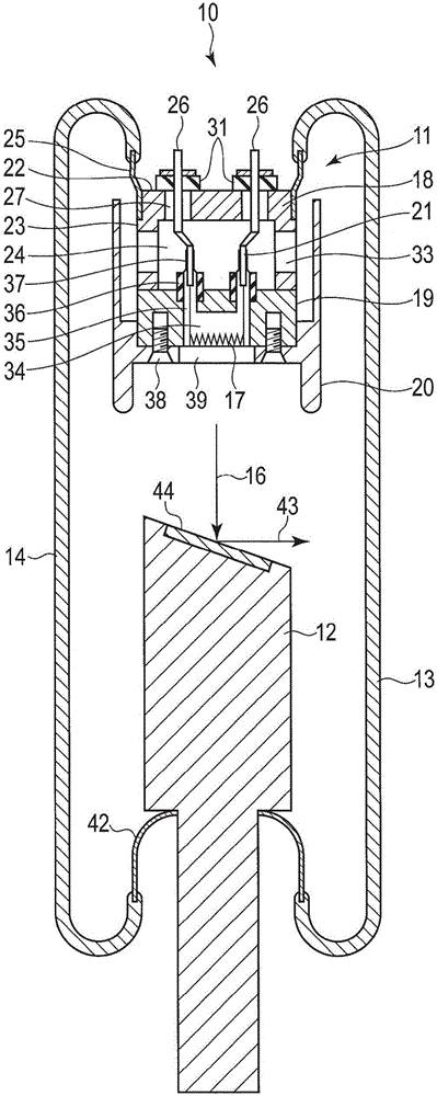
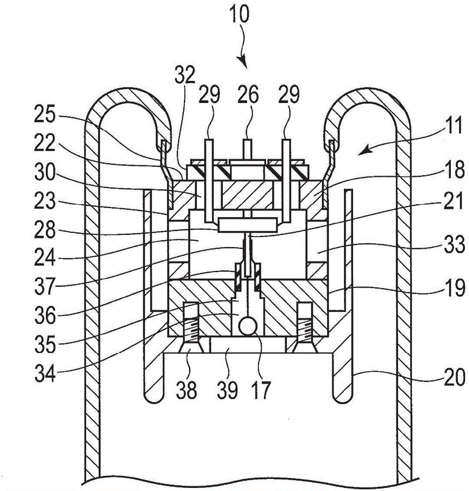
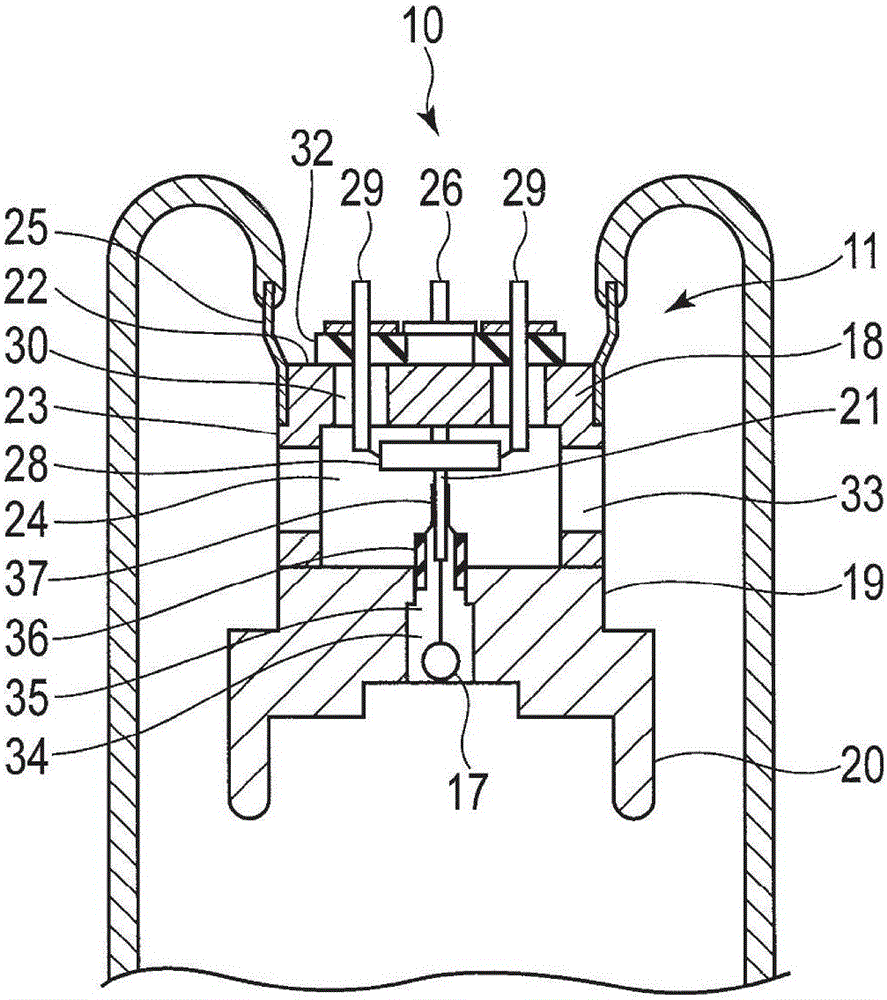
[0012] In summary, one embodiment provides an X-ray tube including: a cathode having a filament emitting an electron beam; an anode target injected into the electron beam to emit X-rays; and a vacuum envelope, The cathode and the anode target are housed inside the vacuum envelope. The cathode has a metal lead support body that constitutes a part of the vacuum envelope and is exposed to the outside of the vacuum envelope, and is attached such that a lead wire that supplies electricity to the filament passes through the vacuum enclosure. and a metallic filament support fixed to the lead support so as to contact the lead support and supporting the filament.

[0013] Below, refer to figure 1 and figure 2 The first embodiment will be described.

[0014] Such as figure 1 and figure 2 As shown, the X-ray tube 10 is a fixed anode type X-ray tube, and has a cathode 11, an anode target 12, and a vacuum envelope 13 that accommodates the cathode 11 and the anode target 12. The vac...


PUM


Abstract

According to one embodiment, an X-ray tube includes a cathode including a filament, an anode target, and an envelope. The cathode includes a metal lead wire supporter which is exposed outside the envelope, which is configured a part of the envelope, and to which a lead wire as a power supplier to the filament is attached such that the lead wire passes both inside and outside of the envelope, and a metal filament supporter fixed on the lead wire supporter, being in contact with the lead wire supporter, and supporting the filament.

Description

[0001] This application claims priority from Japanese Patent Application No. 2015-117322 filed on June 10, 2015, the entire contents of which are incorporated herein by reference. technical field [0002] The present invention relates to X-ray tubes. Background technique [0003] In an X-ray tube, in order to manage the X-ray focus size, it is necessary to strictly manage the position of the filament relative to the cathode cup. In the existing structure, the filament is fixed in the cathode cup through an insulator such as steatite or ceramics. [0004] On the other hand, in order to energize the filament from the outside of the X-ray tube, the lead wire is passed through the glass container of the vacuum envelope. One or two of the leads are connected to the filament, but the rest are fixed to the cathode cap which supports the cathode cup. [0005] When the X-ray tube is in operation, the filament is used at a temperature exceeding 2000° C. Therefore, cathode components...

Claims


Application Information

Patent Timeline
IPC IPC(8): H01J35/06
CPCH01J35/066H01J1/18H01J5/22H01J5/26H01J19/48H01J19/60H01J19/66H01J29/90H01J29/92H01J35/06H01J2235/023H01J35/165H01J2237/032H01J2237/166H01J2893/0008H05G1/10
Inventor 高桥直树下野隆阿武秀郎
Owner CANON ELECTRON TUBES & DEVICES CO LTD
Why Eureka
Try Eureka