Wall flow exhaust particle filtering and electricalloy heating post-regeneration treating device for diesel engine

A post-processing device and wall-flow technology, applied in exhaust devices, noise reduction devices, mechanical equipment, etc., can solve the problems of high fuel quality requirements, complex structure, easy catalyst poisoning, etc., and achieve significant social and economic benefits. High filtration efficiency and vibration reduction effect

Inactive Publication Date: 2004-12-15
SHANGHAI JIAO TONG UNIV
View PDF1 Cites 17 Cited by
  • Summary
  • Abstract
  • Description
  • Claims
  • Application Information

AI Technical Summary

Problems solved by technology

[0003] Among these devices, electrostatic trapping and cyclone separation are used to trap diesel engine particles, and then through forced regeneration, fuel injection (gas) combustion-supporting regeneration, microwave heating regeneration and reverse jet regeneration, the structure is complex, the work is unreliable, and the cost is high. , it is difficult to promote the use of
The catalyst of the device that continuously regenerates through oxidation catalysis is prone to poisoning, has high requirements on fuel quality, and has a short service life.
In the existing technology, the utility model patent with the patent number ZL00243080.0-diesel engine exhaust particulate filter microwave regeneration device is composed of a filter body, a microwave source, a microwave power supply, a transmission waveguide and a secondary air device that can supply air to the filter body , the microwave source communicates with the filter regeneration cavity through the transmission waveguide. The transmission waveguide is connected with the exhaust pipe of the diesel engine, and the air is drawn from the original air device of the diesel engine to form a secondary air device. It communicates with the filter regeneration cavity. The structure of the device is complex and requires a relatively high cost High microwave and secondary air devices, high cost, difficult to popularize and apply

Method used


Image

  • Wall flow exhaust particle filtering and electricalloy heating post-regeneration treating device for diesel engine

Examples


Embodiment Construction

[0008] The specific implementation of the present invention will be further described below in conjunction with the accompanying drawings.

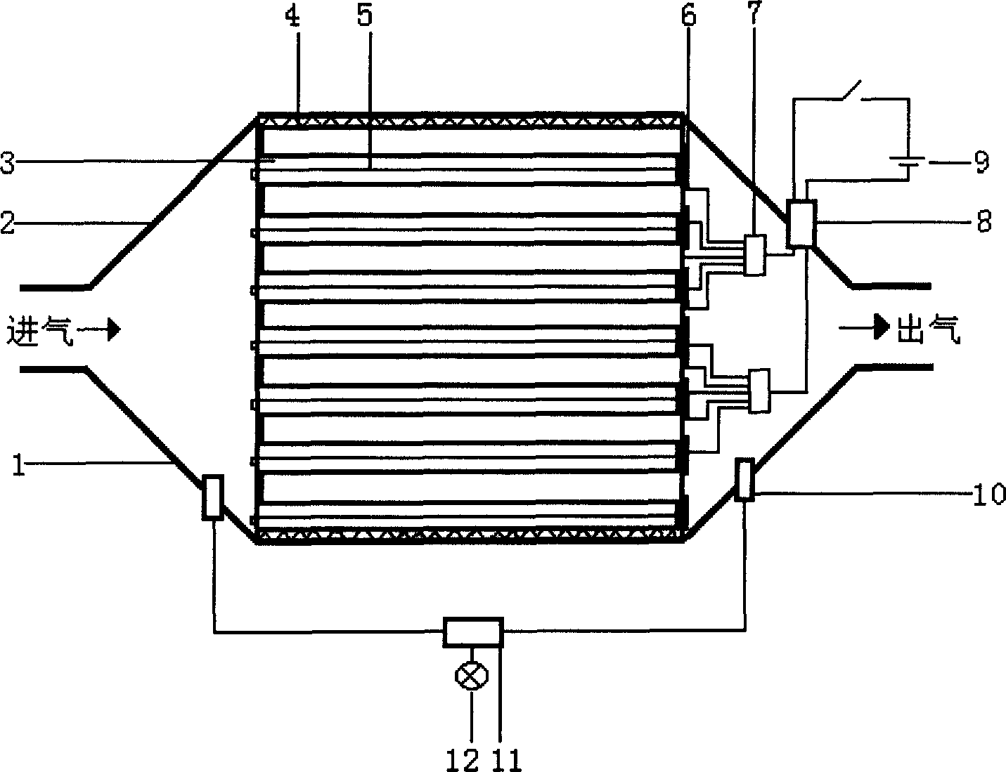
[0009] Such as figure 1 As shown, the present invention mainly includes: lower housing 1, upper housing 2, wall-flow honeycomb ceramics 3, metal wire 4, heating wire 5, connecting piece 6, metal chuck 7, conduit 8, power supply 9, pressure sensor 10. Electronic control device 11, warning light 12, the wall-flow honeycomb ceramic 3 is cylindrical, and the holes at the inlet end are blocked alternately. After the exhaust gas of the diesel engine enters from the inlet end of the wall-flow honeycomb ceramic Particles are filtered when the micropores on the top pass through, and the heating wire 5 is made into a U shape. The heating wire 5 is inserted from the air inlet direction along the adjacent diagonal filter holes of the wall-flow honeycomb ceramic 3, and passes through the outlet end of the wall-flow honeycomb ceramic 3. The connecting...


PUM


Abstract

The wall flow type exhaust particle filtering and electrically heating post-regeneration treating device for diesel engine includes mainly lower casing, upper casing, wall flow type honeycombed ceramic, metal filament, heating wire, connecting sheet, canal, power source, pressure sensor, electric controller and warning lamp. The wall flow type honeycombed ceramic is installed inside the post-treating unit casing with one metal wire layer in between. The U-shaped heating wire is inserted into the filtering holes along the wall flow type honeycombed ceramic and connected via the connecting sheet to the wall flow type honeycombed ceramic, with the heating wires in different areas are connected parallelly. Pressure sensors are installed on two ends of the lower casing, and when pressure difference reaches some value, the particle is regenerated. The device has high filtering efficiency, complete regeneration, long ceramic life, high reliability and low cost.

Description

technical field [0001] The invention relates to a diesel engine exhaust particle aftertreatment device, in particular to an electrothermal regeneration aftertreatment device for diesel engine exhaust particle wall flow filtration, and belongs to the technical field of diesel engine exhaust purification treatment. Background technique [0002] Diesel engine is a kind of power machinery with wide application, high demand and high thermal efficiency. However, the harmful emission particles it emits are much higher than gasoline engines, especially the particles with a diameter of 0.01-10 microns are carcinogenic. These particles It often floats at the height of people's breathing, and it is easy to be inhaled into the lungs, which greatly threatens human health. In the case that the pre-treatment and internal treatment of the diesel engine have little effect, the post-treatment of diesel exhaust particulates is often an effective and economical method. There are many after-tre...

Claims


Application Information

Patent Timeline
Patent Type & Authority Applications(China)
IPC IPC(8): F01N3/027
Inventor 黄震李孝禄刘洪胜陈志吴君华
Owner SHANGHAI JIAO TONG UNIV
Why Eureka
Try Eureka