
Automatic sheet lamination device for motor rotor and stator

A technology of lamination devices and motor rotors, which is applied in the direction of electromechanical devices, electric components, and manufacturing motor generators, etc., can solve the problems of increasing labor operating costs, high production costs, and high labor intensity of workers, so as to reduce the cost of equipment and labor input, reducing intermediate circulation links, and reducing the labor intensity of workers

Active Publication Date: 2016-12-21
HUZHOU YUEQIU MOTOR
View PDF5 Cites 1 Cited by
  • Summary
  • Abstract
  • Description
  • Claims
  • Application Information

AI Technical Summary

Problems solved by technology

At present, after the stamping of the stator and rotor sheets on different machines, they need to be packaged first, and then transported to the corresponding lamination device for stamping and lamination, which increases the intermediate circulation link, which not only increases the labor cost of workers. It is labor intensive and time-consuming, which reduces the production efficiency of the stator and rotor; and the stator and rotor are stamped on different equipment, and two different equipment are required for stamping, which will double the labor force, The investment in equipment and operating costs increases the production cost of the enterprise
In addition, during the lamination process, the stator sheets and rotor sheets are manually put into the corresponding lamination device one by one, and then the worker will press and fix the machine by operating the machine. The gap is difficult to locate, and it must be placed manually every time. Not only is the operation complicated, but also the efficiency is low. It is also difficult to ensure the uniformity of the stator and rotor pieces, resulting in uneven stamping quality of the stator and rotor
Therefore, the existing lamination stamping equipment has problems such as low production efficiency, high labor intensity, high production cost, inaccurate positioning and uneven product quality.

Method used


Image

  • Automatic sheet lamination device for motor rotor and stator
  • Automatic sheet lamination device for motor rotor and stator
  • Automatic sheet lamination device for motor rotor and stator

Examples


Embodiment Construction

[0018] The present invention will be further described below in conjunction with the drawings and embodiments, but it will not serve as a basis for limiting the present invention.

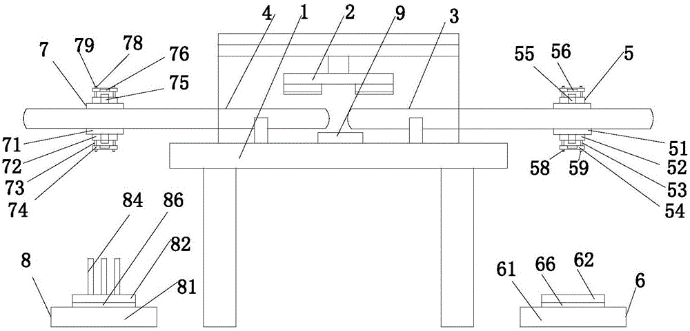
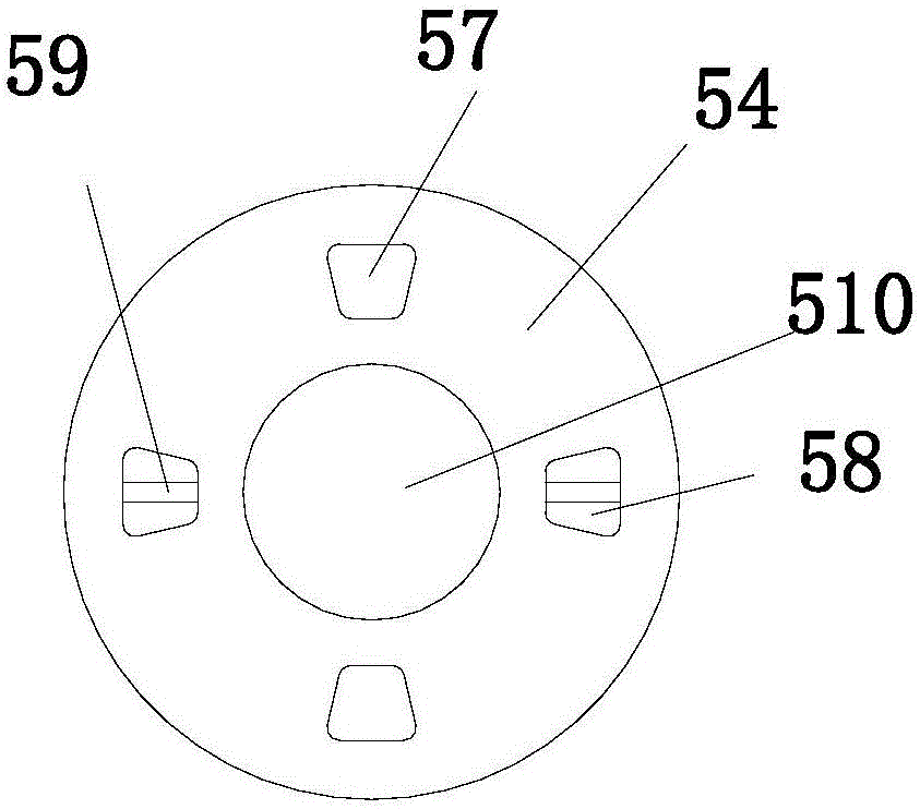
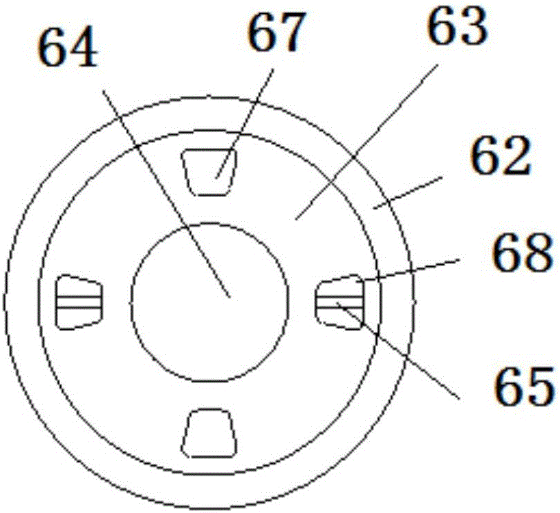
[0019] Examples. An automatic lamination device for motor rotor and stator, which is composed as Figure 1 to Figure 5 As shown, it includes a frame 1. The frame 1 is provided with a stator sheet output device 3 and a rotor sheet output device 4 corresponding to the punching equipment 2, and the stator sheet output device 3 is provided with a stator punching piece fixing component 5, the stator sheet A stator lamination device 6 is provided below the output device 3, a rotor punching fixing part 7 is provided on the rotor sheet output device 4, and a rotor lamination device 8 is provided below the rotor sheet output device 4; the rotor punching fixing part 7 includes a set of first base 71 fixed on the rotor sheet output device 4, the first base 71 is provided with a first rotating seat 72, the first...


PUM


Abstract

The invention discloses an automatic sheet lamination device for a motor rotor and stator. The automatic sheet lamination device comprises a rack (1); the rack (1) is provided with a stator sheet output device (3) and a rotor sheet output device (4); the stator sheet output device (3) is provided with a stator punched sheet fixing component (5); a stator sheet lamination device (6) is arranged below the stator sheet output device (3); the rotor sheet output device (4) is provided with a rotor punched sheet fixing component (7); and a rotor sheet lamination device (8) is arranged below the rotor sheet output device (4). With the automatic sheet lamination device for the motor rotor and stator of the invention adopted, production efficiency can be improved, labor intensity can be reduced, production cost can be reduced, positioning is accurate, and product quality can be improved.

Description

Technical field [0001] The invention relates to a lamination device, in particular to an automatic lamination device for motor rotors and stators. Background technique [0002] The motor is mainly composed of components such as a stator, a rotor, and a casing, while the stator and rotor are assembled by stator and rotor plates respectively. At present, after the stator and rotor plates are stamped on different machines, they need to be packaged first, and then transported to the corresponding lamination device for stamping and lamination, which increases the intermediate circulation links, which not only increases the workers’ It is labor-intensive and time-consuming, which reduces the production efficiency of the stator and the rotor; and the stator and the rotor are stamped in different equipment, which requires two different equipment for stamping, which will double the labor, The investment in equipment and operating costs has increased the production costs of enterprises. ...

Claims


Application Information

Patent Timeline
Patent Type & Authority Applications(China)
IPC IPC(8): H02K15/02
CPCH02K15/024
Inventor 史国强钟大志朱国良张建军陈锋
Owner HUZHOU YUEQIU MOTOR
Learn More