Fuel pump shell machining clamp

A fuel pump and housing technology, which is applied in the direction of manufacturing tools, metal processing equipment, metal processing machinery parts, etc., can solve the problems of easy deformation of the workpiece, achieve the effect of simple and compact structure, and overcome unevenness

Inactive Publication Date: 2016-12-28
宁波爱得信机械部件有限公司
View PDF9 Cites 1 Cited by
  • Summary
  • Abstract
  • Description
  • Claims
  • Application Information

AI Technical Summary

Problems solved by technology

Using the traditional three-jaw fixture to clamp the fuel pump casing for processing has the disadvantage that the workpiece is prone to deformation. Therefore, a fuel pump casing processing fixture for clamping the fuel pump casing without deformation of the workpiece is designed. become an urgent problem

Method used


Image

  • Fuel pump shell machining clamp
  • Fuel pump shell machining clamp

Examples


Embodiment 1

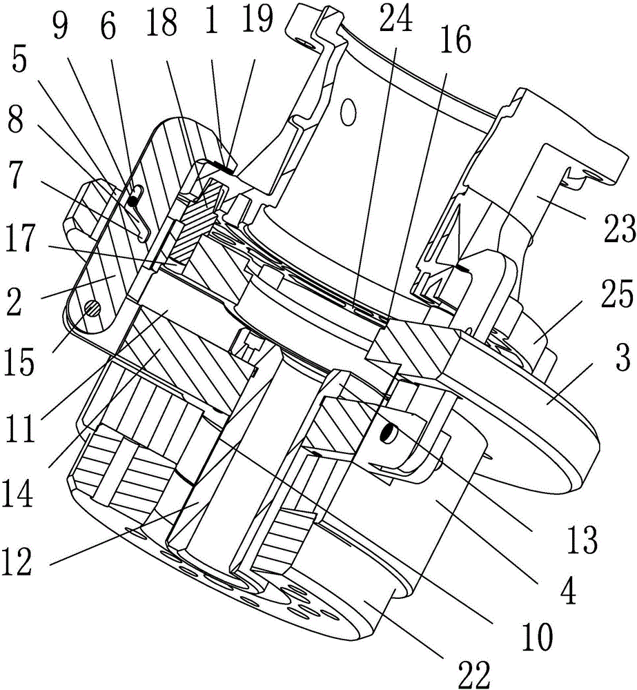
[0016] Embodiment 1, as attached figure 1 Shown: a fuel pump housing processing fixture, including: three pressure rods 2 with claw feet 1 at the front end, a positioning plate 3, a connecting column 4 screwed to the rear end of the positioning plate 3 at the front end, and a pressure rod driving device; Positioning plate 3 is provided with end through hole 5 that number is the same as 2 numbers of pressure rods and is evenly distributed along the circumference; Rod drive connection.

[0017] The cross-sectional shape of the end through hole 5 is a rectangle whose length direction is the radial direction of the positioning plate 3; the cross-sectional shape of the pressure rod 2 is a rectangle whose thickness matches the width of the end through hole 5; Guide through groove is arranged; Guide through groove comprises: outer groove 6, be positioned at the inner groove 7 of outer groove 6 rear side, inclined groove 8; One end of inclined groove 8 is communicated with the rear e...

Embodiment 2

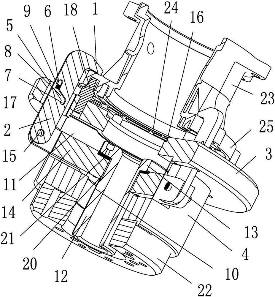
[0021] Embodiment 2, as attached figure 2 Shown: a fuel pump housing processing fixture, including: three pressure rods 2 with claw feet 1 at the front end, a positioning plate 3, a connecting column 4 screwed to the rear end of the positioning plate 3 at the front end, and a pressure rod driving device; Positioning plate 3 is provided with end through hole 5 that number is the same as 2 numbers of pressure rods and is evenly distributed along the circumference; Rod drive connection.

[0022] The cross-sectional shape of the end through hole 5 is a rectangle whose length direction is the radial direction of the positioning plate 3; the cross-sectional shape of the pressure rod 2 is a rectangle whose thickness matches the width of the end through hole 5; Guide through groove is arranged; Guide through groove comprises: outer groove 6, be positioned at the inner groove 7 of outer groove 6 rear side, inclined groove 8; One end of inclined groove 8 is communicated with the rear ...


PUM


Abstract

The invention relates to the field of machining clamps, and is aimed at providing a fuel pump shell machining clamp which comprises a plurality of pressing rods with claws at front ends and further comprises a positioning plate, a connecting column and a pressing rod driving device. The front end of the connecting column is connected with the rear end of the positioning plate. End through holes which are circumferentially distributed are formed in the positioning plate, and the number of the end through holes is the same as the number of the pressing rods. The pressing rods correspond to the end through holes one to one. The rear ends of the pressing rods penetrate through the end through holes and are connected with the pressing rod driving device. When the fuel pump shell machining clamp is used, the rear end of the connecting column is connected with a connecting flange of a machine tool, a fuel pump shell is placed at the front end of the positioning plate for positioning, the pressing rod driving device pulls the pressing rods to move backwards, and the claws press the front end of the flange of the fuel pump shell for clamping. The fuel pump shell machining clamp clamps the fuel pump shell for machining, and a workpiece can not deform.

Description

technical field [0001] The invention relates to the field of machining fixtures, in particular to a machining fixture for a fuel pump casing. Background technique [0002] The side wall of the housing of the fuel pump is thin and is provided with a flange; the utility model of Chinese patent application number CN201420149522.3 discloses a three-jaw clamp, which includes a cylindrical jacket and three jaws. The inside of the cover is provided with a lifting device, and the three jaws are slidably arranged on the top of the cylindrical jacket, and the three jaws are arranged in a circular array on the top of the cylindrical jacket, and the top of the lifting device is located at the top of the three clamps The central position of the annular array formed by the claws, the present invention can evenly spread the three clamping claws outwards to fix the workpiece through the front top of the cone head, and the workpiece is evenly stressed in all directions. Using the traditiona...

Claims


Application Information

Patent Timeline
Patent Type & Authority Applications(China)
IPC IPC(8): B23Q3/00
CPCB23Q3/00B23Q2703/04B23Q2703/10
Inventor 顾继跃陆琦
Owner 宁波爱得信机械部件有限公司
Why Eureka
Try Eureka