Unlock instant, AI-driven research and patent intelligence for your innovation.
Forced cooling process and device for regeneration process
What is Al technical title?
Al technical title is built by PatSnap Al team. It summarizes the technical point description of the patent document.
A technology of forced cooling and regeneration process, applied in chemical/physical process, catalyst regeneration/reactivation, physical/chemical process catalyst, etc., can solve the problem of long regeneration time, achieve fast regeneration speed, low cost and short downtime Effect
Active Publication Date: 2017-01-04
CONNELL CHEM IND
View PDF5 Cites 0 Cited by
Summary
Abstract
Description
Claims
Application Information
AI Technical Summary
This helps you quickly interpret patents by identifying the three key elements:
Problems solved by technology
Method used
Benefits of technology
Problems solved by technology
The existing problem is that the regeneration time is long, the average shutdown time during the entire regeneration period is 100 hours, and the longest regeneration shutdown time is 173 hours, which becomes an unfavorable factor affecting the continuous high-load production of aniline
Method used
Image
Click on the blue label to locate the original text in one second.
Reading with bidirectional positioning of images and text.
Examples
Embodiment 2
[0041] Embodiment 2, compared with embodiment 1, the process and the device used in this embodiment are the same, the difference is that the process parameters are different, and the specific steps are as follows:
[0042] 1) The beginning stage of regeneration;
[0043] Open the first pipeline 1 and the second pipeline 2, open the regeneration circuit, and use 0-3000Nm 3 / h flow into the air for regeneration, the temperature of the fluidized bed 101 rises from 180°C to 400-430°C, and at the same time, open the third pipeline 3 and the fourth pipeline 4, so that the production circuit is open and vacant;
[0044] 2) Regeneration constant temperature stage;
[0045] ①The temperature of the fluidized bed 101 rises to 400-430°C to enter the regeneration constant temperature stage, the third pipeline 3 is closed, the fifth pipeline 5, the seventh pipeline 7, and the sixth pipeline 6 are opened, and the forced cooling circuit is opened;
[0053] Embodiment 3, this embodiment is compared with embodiment 1, and technological process and used device are identical, and difference is: process parameter is different, and concrete steps are as follows:
[0054] 1) The beginning stage of regeneration;
[0055] Open the first pipeline 1 and the second pipeline 2, open the regeneration circuit, and use 0-3000Nm 3 / h flow into the air for regeneration, the temperature of the fluidized bed 101 rises from 180°C to 400-430°C, and at the same time, open the third pipeline 3 and the fourth pipeline 4, so that the production circuit is open and vacant;
[0056] 2) Regeneration constant temperature stage;
[0057] ①The temperature of the fluidized bed 101 rises to 400-430°C to enter the regeneration constant temperature stage, the third pipeline 3 is closed, the fifth pipeline 5, the seventh pipeline 7, and the sixth pipeline 6 are opened, and the forced cooling circuit is opened;
PUM
Abstract
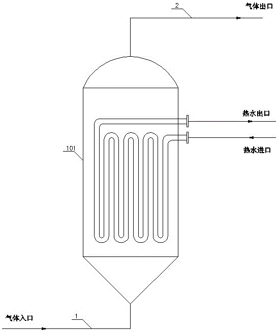
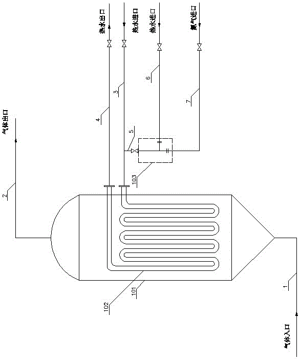
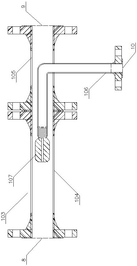
The invention discloses a forced cooling process and device for the regeneration process. The forced cooling process is characterized by including a regeneration starting stage, a regeneration constant-temperature stage, a regeneration cooling stage and a normal production stage. The device structurally comprises a fluidized bed 101 and a steam water atomizer 103, a gas inlet at the bottom of the fluidized bed 101 is connected with a first pipeline 1 while a gas outlet at the top of the same is connected with a second pipeline 2, a hot water circulating pipe 102 is arranged in the fluidized bed 101, and an inlet of the hot water circulating pipe 102 is connected with a third pipeline 3 while an outlet of the same is connected with a fourth pipeline 4; a mixed gas outlet at the top end of the steam water atomizer 103 is connected with a fifth pipeline 5 and connected with the third pipeline 3 through the same while a nitrogen inlet at the bottom end of the same is connected with a seventh pipeline 7 and connected with a nitrogen pipeline through the same, and the end of a hot water incoming pipe 106 on the side face of the steam water atomizer 103 is connected with a sixth pipeline 6 and connected with a hot water system through the same.
Description
technical field [0001] The invention relates to the production of aniline, which is a forced cooling process and device used in the regeneration process. It is used for the catalyst regeneration of the aniline production in a fluidized bed, and the forced cooling of the fluidized bed in the regeneration state is performed to shorten the regeneration time of the catalyst. Background technique [0002] When using a fluidized bed to produce aniline, it is necessary to stop production regularly to burn and clean the carbon deposits on the surface of the catalyst to restore the activity of the catalyst, which is the regeneration process. The specific process of regeneration is: the air enters the fluidized bed 101 through the pipeline 1, and the oxygen in it contacts with the carbon deposit on the surface of the catalyst for combustion, takes away part of the heat, and discharges it through the pipeline 2 to keep the temperature of the fluidized bed 101 stable. . The amount of a...
Claims
Application Information
Patent Timeline
Application Date:The date an application was filed.
Publication Date:The date a patent or application was officially published.
First Publication Date:The earliest publication date of a patent with the same application number.
Issue Date:Publication date of the patent grant document.
PCT Entry Date:The Entry date of PCT National Phase.
Estimated Expiry Date:The statutory expiry date of a patent right according to the Patent Law, and it is the longest term of protection that the patent right can achieve without the termination of the patent right due to other reasons(Term extension factor has been taken into account ).
Invalid Date:Actual expiry date is based on effective date or publication date of legal transaction data of invalid patent.
