A forced cooling process and device for regeneration process

A technology of forced cooling and regeneration process, which is applied in the direction of chemical/physical process, catalyst regeneration/reactivation, physical/chemical process catalyst, etc. It can solve the problems of long regeneration time and achieve fast regeneration speed, low cost and good effect Effect

Active Publication Date: 2018-10-09
CONNELL CHEM IND
View PDF5 Cites 0 Cited by
  • Summary
  • Abstract
  • Description
  • Claims
  • Application Information

AI Technical Summary

Problems solved by technology

The existing problem is that the regeneration time is long, the average shutdown time during the entire regeneration period is 100 hours, and the longest regeneration shutdown time is 173 hours, which becomes an unfavorable factor affecting the continuous high-load production of aniline

Method used


Image

  • A forced cooling process and device for regeneration process
  • A forced cooling process and device for regeneration process
  • A forced cooling process and device for regeneration process

Examples


Embodiment 2

[0041] Embodiment 2, this embodiment is compared with embodiment 1, the technological process and the used device are the same, the difference is: the technological parameters are different, and the specific steps are as follows:

[0042] 1) The beginning of regeneration;

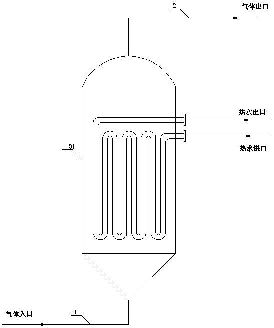
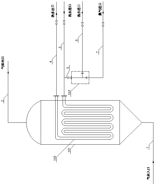
[0043] Open the first pipeline 1 and the second pipeline 2, open the regeneration circuit, and set the pressure to 0-3000Nm 3 The flow rate of / h is passed into the air for regeneration, the temperature of the fluidized bed 101 is raised from 180 ° C to 400 to 430 ° C, and at the same time, the third pipeline 3 and the fourth pipeline 4 are opened, so that the production loop is open and vacant;

[0044] 2) Regeneration constant temperature stage;

[0045] ①The temperature of the fluidized bed 101 rises to 400~430℃ and enters the regeneration constant temperature stage, closes the third pipeline 3, opens the fifth pipeline 5, the seventh pipeline 7, and the sixth pipeline 6, and opens the forced cooling ci...

Embodiment 3

[0053] Embodiment 3, this embodiment is compared with embodiment 1, the technological process and the used device are the same, the difference is: the technological parameters are different, and the specific steps are as follows:

[0054] 1) The beginning of regeneration;

[0055] Open the first pipeline 1 and the second pipeline 2, open the regeneration circuit, and set the pressure to 0-3000Nm 3 The flow rate of / h is passed into the air for regeneration, the temperature of the fluidized bed 101 is raised from 180 ° C to 400 to 430 ° C, and at the same time, the third pipeline 3 and the fourth pipeline 4 are opened, so that the production loop is open and vacant;

[0056] 2) Regeneration constant temperature stage;

[0057] ①The temperature of the fluidized bed 101 rises to 400~430℃ and enters the regeneration constant temperature stage, closes the third pipeline 3, opens the fifth pipeline 5, the seventh pipeline 7, and the sixth pipeline 6, and opens the forced cooling ci...


PUM


Abstract

The present invention is a kind of forced cooling process and device used in the regeneration process, which is characterized in that it includes the regeneration start stage, the regeneration constant temperature stage, the regeneration cooling stage, and the normal production stage. The structure of the device used is: it includes a fluidized bed 101 The gas inlet at the bottom of the fluidized bed 101 is connected to the first pipeline 1, and the gas outlet at the top is connected to the second pipeline 2. The fluidized bed 101 has a built-in hot water circulation pipe 102, and the inlet of the hot water circulation pipe 102 is connected to the third pipeline. The pipeline 3 is connected, the outlet is connected to the fourth pipeline 4, and a steam-water atomizer 103 is also included. The mixed gas outlet at the top of the steam-water atomizer 103 is connected to the fifth pipeline 5, and the fifth pipeline 5 is connected to the third pipeline 3 Connection, the nitrogen inlet at the bottom of the soda atomizer 103 is connected to the seventh pipeline 7, and connected to the nitrogen pipeline through the seventh pipeline 7, the end of the hot water inlet pipe 106 on the side of the soda atomizer 103 is connected to the sixth pipeline 6, And connect with the hot water system through the sixth pipeline 6.

Description

technical field [0001] The invention relates to the production of aniline, and is a forced cooling process and a device for the regeneration process, which is used for the regeneration of a catalyst for producing aniline in a fluidized bed, and the fluidized bed in a regenerated state is forcedly cooled to shorten the catalyst regeneration time. Background technique [0002] When using a fluidized bed to produce aniline, it is necessary to periodically stop production to clean up the carbon deposits on the surface of the catalyst to restore the activity of the catalyst, which is the regeneration process. The specific process of regeneration is: the air enters the fluidized bed 101 through the pipeline 1, and the oxygen in it contacts the carbon deposits on the surface of the catalyst for combustion, takes away part of the heat, and is discharged through the pipeline 2 to keep the temperature of the fluidized bed 101 stable. . The amount of air entering the fluidized bed thr...

Claims


Application Information

Patent Timeline
Patent Type & Authority Patents(China)
IPC IPC(8): B01J38/02B01J38/04B01J38/06B01J38/48B01J8/18
CPCB01J8/1872B01J38/02B01J38/04B01J38/06B01J38/48B01J2219/2408B01J2219/2411B01J2219/2412
Inventor 冷丰强申旭尹春玲高洪东
Owner CONNELL CHEM IND
Why Eureka
Try Eureka