Welding workbench

A workbench and articulated technology, applied in welding equipment, auxiliary welding equipment, welding/cutting auxiliary equipment, etc., can solve the problems of low equipment utilization and welding efficiency, and achieve the improvement of equipment utilization, welding efficiency, rotating accurate positioning

Inactive Publication Date: 2017-01-04
蔡利锋
View PDF0 Cites 0 Cited by
  • Summary
  • Abstract
  • Description
  • Claims
  • Application Information

AI Technical Summary

Problems solved by technology

[0003] The purpose of the present invention is to provide a welding workbench, which can solve the problems of low welding efficiency and low equipment utilization in existing welding work stations

Method used


Image

  • Welding workbench
  • Welding workbench

Examples


Embodiment Construction

[0011] The present invention will be described in further detail below in conjunction with accompanying drawing embodiment:

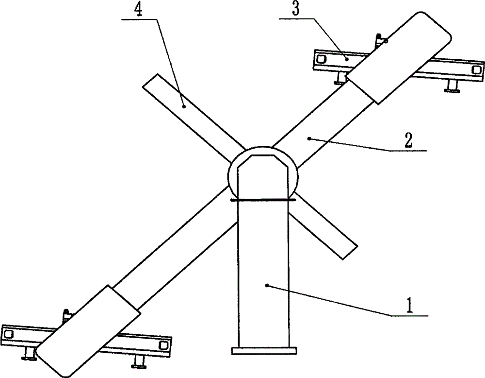
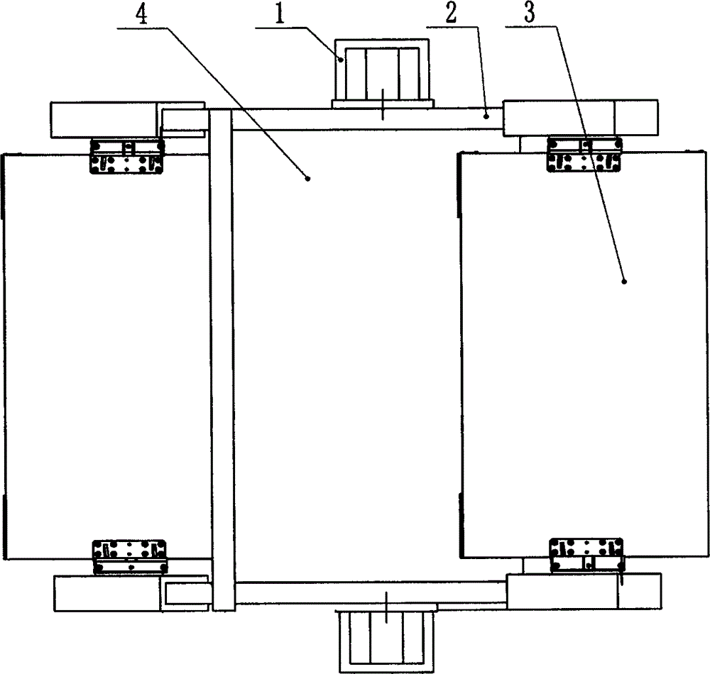
[0012] figure 1 with figure 2 The shown welding workbench mainly includes a support frame, a rotary drive device, a rotating arm 2, a welding workbench 3, and a protective plate 4. The support frame includes two opposite columns 1, and the rotary drive device is installed on one of the column 1 Inside, the rotary driving device of this embodiment is a reducer controlled by a controller, the controller and the reducer are electrically connected through a control switch, and shafts are arranged opposite to each other at the same height positions of the two columns 1, and each column 1 The rotating arm 2 is hinged around the corresponding axis, the rotating drive device is installed on the column 1, the output shaft of the reducer is connected to the rotating arm 2, and a welding work is installed between the two ends of the rotating arm 2 respectively. ...


PUM


Abstract

The invention provides a welding workbench which comprises a supporting frame and rotation driving devices controlled by a controller. The supporting frame comprises two stand columns arranged oppositely, rotating arms are hinged to the two stand columns correspondingly, and the rotation driving devices are mounted on the stand columns. Output shafts of the rotation driving devices are connected with the corresponding rotating arms, and welding workbench bodies are mounted at the two ends of the rotating arms correspondingly and located between the two rotating arms. The welding workbench is highly affirmed by operators in use, and is convenient to use.

Description

technical field [0001] The invention relates to the technical field of welding equipment, in particular to a welding workbench. Background technique [0002] Existing welding operations mostly use a single welding workstation to work, and it is necessary to disassemble and weld the workpiece at the same station, that is, after welding a workpiece, it must be disassembled and then welded to the next workpiece. This welding workstation The following disadvantages exist: low welding efficiency and low equipment utilization. Bring inconvenience to the operator. Contents of the invention [0003] The purpose of the present invention is to provide a welding workbench, which can solve the problems of low welding efficiency and low equipment utilization in the existing welding workbench. [0004] In order to solve the above-mentioned problems, the technical solution adopted by the present invention is: this welding workbench includes a support frame and a rotary drive device con...

Claims


Application Information

Patent Timeline
Patent Type & Authority Applications(China)
IPC IPC(8): B23K37/00
CPCB23K37/0461B23K37/00
Inventor 蔡利锋
Owner 蔡利锋
Why Eureka
Try Eureka