Automatic complex special-shaped workpiece welding track generation system and method

An automatic welding and trajectory generation technology, applied in welding equipment, auxiliary welding equipment, welding/cutting auxiliary equipment, etc., can solve the problems of thin-walled workpiece contour deformation, positioning error, etc.

Active Publication Date: 2017-01-04
SOUTH CHINA UNIV OF TECH
View PDF6 Cites 15 Cited by
  • Summary
  • Abstract
  • Description
  • Claims
  • Application Information

AI Technical Summary

Problems solved by technology

[0003] Large stress deformation occurs in the welding process of complex special-shaped thin-walled workpieces, and manual spot welding is required to complete the positioning of the workpieces

Method used


Image

  • Automatic complex special-shaped workpiece welding track generation system and method
  • Automatic complex special-shaped workpiece welding track generation system and method
  • Automatic complex special-shaped workpiece welding track generation system and method

Examples


Embodiment 1

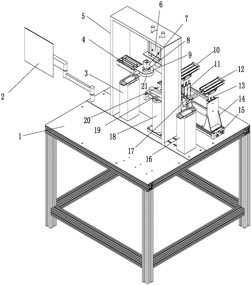
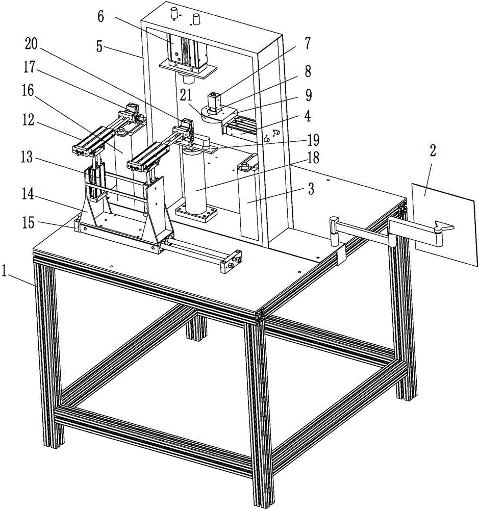
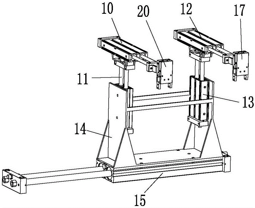
[0066] like Figure 1 to Figure 3 As shown in the figure, an automatic welding trajectory generation system for complex special-shaped workpieces includes a workbench, a workpiece support rotary table for fixing workpieces, a workpiece clamping system for three-axis movement of workpieces, a machine vision measurement system, a touch screen, and a motion Control System,

[0067] The workpiece support turntable and the workpiece clamping system are arranged on the workbench, and the workpiece support turntable includes a rotary servo motor 18 vertically arranged on the workbench 1, a shaft connected to the output shaft of the rotary servo motor 18 Rotating fixture 19; the touch display screen is connected with the motion control system circuit, and fixed on one side of the workbench through the installation arm, and the machine vision measurement system is fixed on the workbench through the machine vision measurement system support platform, and is connected to the workbench th...

Embodiment 2

[0074] A method for automatically generating welding trajectories for complex and special-shaped workpieces based on the system, comprising steps:

[0075] (1) The camera component acquires the image of the workpiece, and preprocesses the acquired image to extract the outline to obtain data points;

[0076] (2) Perform NURBS fitting on the obtained data points to obtain the welding trajectory;

[0077] (3) The motion control system sends corresponding motion pulses to each servo motor in combination with the generated welding trajectory, and drives the welding manipulator to perform corresponding contour welding.

[0078] Specifically, described step (1) specifically includes:

[0079] (11) Obtain the image of the workpiece, and use Halcon to separate, corrode, and extract the skeleton of the image;

[0080] (12) Eliminate the image noise area irrelevant to the welding track;

[0081] (13) Obtain the image outline under the sub-pixel progress;

[0082] (14) Obtain the data...


PUM


Abstract

The invention discloses an automatic complex special-shaped workpiece welding track generation system which comprises a worktable, a workpiece supporting rotary table, a workpiece clamping system, a machine vision measurement system, a touch display screen and a motion control system, wherein the workpiece supporting rotary table is used for fixing a workpiece, and three-axis movement of the workpiece is achieved by the workpiece clamping system. The workpiece supporting rotary table and the workpiece clamping system are arranged on the worktable, the touch display screen is connected with the motion control system through a circuit and fixed on one side of the worktable through a mounting arm, the machine vision measurement system is fixed on the worktable through a machine vision measurement system supporting table and used for acquiring welding tracks according to acquired workpiece images, and the motion control system comprises a motion controller for driving welding manipulators to weld corresponding profiles. The invention further discloses an automatic complex special-shaped workpiece welding track generation method. The automatic complex special-shaped workpiece welding track generation has the advantages of more adapting workpiece types, rapid track generation, high welding quality and the like.

Description

technical field [0001] The invention relates to an automatic welding technology, in particular to a system and a method for generating an automatic welding trajectory of a complex special-shaped workpiece. Background technique [0002] Automatic welding technology has been widely used and improved in the industrial and manufacturing fields, and the development of welding technology has attracted more and more attention from industrial production and manufacturing companies; today, many automatic welding devices for a specific product have appeared on the market, such as An automatic welding device for welding long seams of large container door panels and a welding device for spot welding the outline of the frame. The automatic welding device has high production efficiency, stable work, good welding quality and can be applied to various complex environments. However, most of the automatic welding devices adopt the method of teaching and reproduction, which lacks the ability ...

Claims


Application Information

Patent Timeline
IPC IPC(8): B23K37/02B25J9/16
CPCB23K37/0252B25J9/1653B25J9/1671
Inventor 张铁周仁义
Owner SOUTH CHINA UNIV OF TECH
Why Eureka
Try Eureka