Ultrasonically-assisted grinding wheel grinding grain arrangement strategy and grinding grain thickness cutting model establishment method

An ultrasonic-assisted grinding wheel grinding technology, which is applied in the direction of bonded grinding wheels, abrasive materials, instruments, etc., can solve the problems of redundant abrasive grains, obvious differences, and the lack of a single abrasive grain cutting thickness model, etc., to achieve easy implementation and versatility strong effect

Active Publication Date: 2017-01-04
JIANGSU UNIV OF TECH
View PDF4 Cites 19 Cited by
  • Summary
  • Abstract
  • Description
  • Claims
  • Application Information

AI Technical Summary

Problems solved by technology

However, in reality, the working surface of sintered or electroplated grinding wheels often has redundant or vacant abrasive grains in local areas, and the exposed heights of abrasive grains are significantly different, and the cut thickness of individual abrasive grains at different positions is quite different, which is seriously inconsistent with the ideal assumption. does not match
Due to the above problems and the complexity of ultrasonic-assisted grinding motion characteristics, the existing research has not yet established a single abrasive grain cutting thickness model in ultrasonic-assisted grinding of advanced ceramic materials.

Method used


Image

  • Ultrasonically-assisted grinding wheel grinding grain arrangement strategy and grinding grain thickness cutting model establishment method
  • Ultrasonically-assisted grinding wheel grinding grain arrangement strategy and grinding grain thickness cutting model establishment method
  • Ultrasonically-assisted grinding wheel grinding grain arrangement strategy and grinding grain thickness cutting model establishment method

Examples


Embodiment Construction

[0054] Embodiments of the present invention will be described in detail below in conjunction with the accompanying drawings.

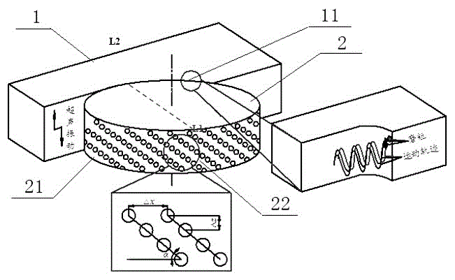
[0055] The working parts of the ultrasonic-assisted grinding wheel include the workpiece 1 to be ground and the grinding wheel 2. The workpiece 1 has a grinding arc area 11, and the side wall of the grinding wheel 2 is a working surface 21. The working surface 21 is in contact with the grinding arc area 11, and the working surface 21 is provided with abrasive grains 22, and the abrasive grains 22 are arranged in an orderly manner on the working surface 21. The control method for the orderly arrangement of the abrasive grains 22 is as follows: sequentially determine the circumferential spacing Δx of the abrasive grains in the working layer, and the abrasive grains Axial spacing Δz, abrasive particle arrangement angle β. The abrasive grain circumferential distance Δx and the abrasive grain axial distance Δz in the working layer are directly related to th...


PUM


Abstract

The invention relates to an ultrasonically-assisted grinding wheel grinding grain arrangement strategy and a grinding grain thickness cutting model establishment method. The single grinding grain movement track during ultrasonically-assisted grinding is taken as the spacial sine curve characteristic, grinding grain circumferential spacing delta x, grinding grain axial spacing delta z and grinding grain arrangement angle beta which can reinforce the grinding wheel working layer grinding grain movement track overlapping action are determined, the control method for ultrasonically-assisted grinding wheel working layer grinding grain arrangement is put up, further the relation between single grain thickness cutting aU[gmax] during ultrasonically-assisted grinding and single grain thickness cutting a[gmax] during ordinary grinding is established according to the calculation method of the grinding layer average volume, and then the aU[gmax] is obtained according to the a[gmax]. Accurate control of the single grain grinding thickness cutting in the ultrasonically-assisted grinding process is realized so that accurate control of the processing surface quality is realized, and the defect that the existing ultrasonically-assisted grinding processing surface quality mainly depends on project practical experience is overcome.

Description

technical field [0001] The invention relates to the technical field of ultrasonic-assisted grinding, in particular to an arrangement strategy of ultrasonic-assisted grinding wheel abrasive grains and a method for establishing a cutting thickness model of abrasive grains. Background technique [0002] Ultrasonic-assisted grinding is a composite processing technology integrating grinding and ultrasonic processing, and has broad application prospects in the processing of hard and brittle materials. The key to obtaining a high-quality machined surface of hard and brittle materials such as advanced ceramics is to control the cut thickness of a single abrasive grain in the ultrasonic-assisted grinding process to be less than the critical cut thickness of the brittle-ductile transition to achieve grinding in the ductile zone. The distribution of abrasive grains in the working layer of the grinding wheel directly determines the cutting thickness of a single abrasive grain in the pro...

Claims


Application Information

Patent Timeline
IPC IPC(8): B24D5/00B24B1/04G06F17/50
CPCB24B1/04B24D5/00G06F30/17G06F30/20
Inventor 丁凯崔方方李奇林傅玉灿苏宏华雷卫宁徐鸿翔
Owner JIANGSU UNIV OF TECH
Why Eureka
Try Eureka