High speed gravure printing machine

A gravure printing machine, high-speed technology, applied in the direction of gravure rotary printing machine, printing machine, rotary printing machine, etc., can solve the problems of high consumption of air conditioning system, defective products or uneven printing, non-parallel installation of guide rollers, etc. Improve overprint accuracy, good effect, and improve the effect of printing

Active Publication Date: 2018-07-31
ZHEJIANG MEIGE MACHINERY
View PDF5 Cites 0 Cited by
  • Summary
  • Abstract
  • Description
  • Claims
  • Application Information

AI Technical Summary

Problems solved by technology

[0002] The existing unit-type gravure printing machine has the following disadvantages: the overprint accuracy of the unit-type gravure printing machine is the key to ensure the printing quality, and among the many factors affecting the overprint accuracy, the most influential point is the parallelism between the guide rollers, As well as the embossing device, oven heating device, etc., there will be cumulative assembly errors, the installation accuracy is not high, and the installation of the guide rollers is not parallel, thus affecting the overprinting accuracy
Due to thermal expansion and contraction, the paper will shrink differently on different surfaces with temperature changes, and the printing substrate will be deformed. At present, it is troublesome to adjust the viscosity of the printing ink according to the temperature and humidity changes of the printing substrate.
There is also a problem to adjust the air-conditioning system of the entire workshop to consume high energy consumption, which increases the production cost of the enterprise
[0004] At the same time, during the operation of the entire gravure printing machine, due to friction, temperature and other reasons, it will change its running speed during the operation process, resulting in defective products or uneven printing, which will affect the printing quality.

Method used


Image

  • High speed gravure printing machine
  • High speed gravure printing machine
  • High speed gravure printing machine

Examples


Embodiment

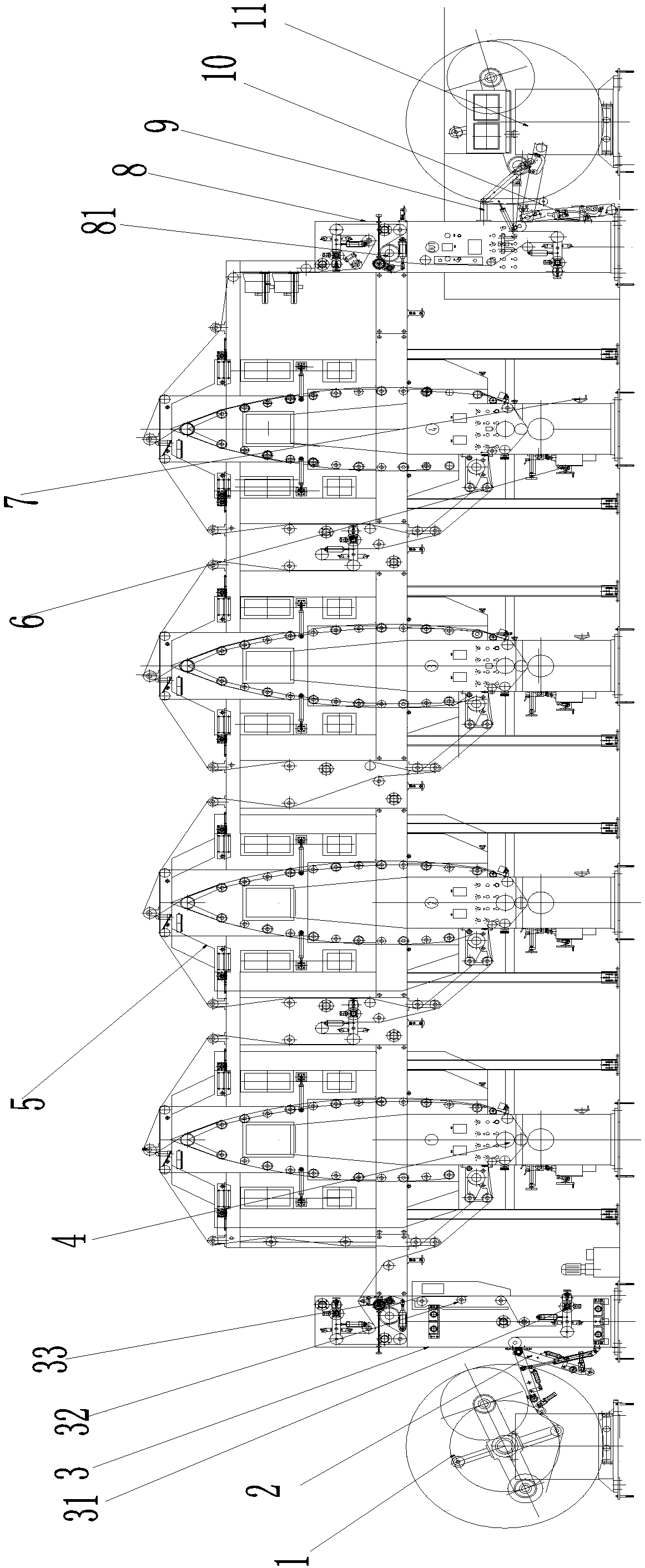
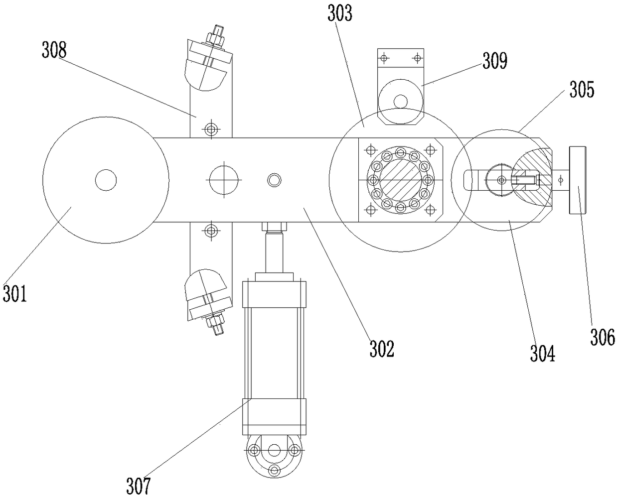
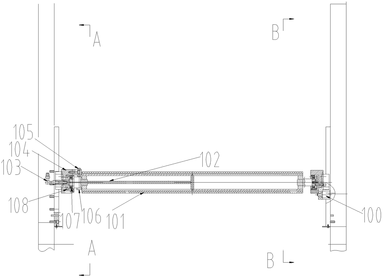
[0029] Refer to attached figure 1 As shown, the high-speed gravure printing machine disclosed in the present invention includes a winding device 11, an unwinding device 1 and at least one set of embossing devices between the rewinding device and the unwinding device, and each group of embossing devices consists of The printing device 4 and the oven heating device 5 are composed of each group of embossing devices connected by transmission guide rollers, and the unwinding traction part 3 connected by transmission guide rollers is installed between the embossing device 4 and the unwinding device, and the embossing device Between the rewinding device and the rewinding device, a rewinding traction section 8 connected by a transmission guide roller is installed, and at least one pendulum roller device 31 for controlling the tension of the printing substrate is arranged on the unwinding traction section 3 and the rewinding traction section 9 , the printing device includes a back pres...


PUM


Abstract

The invention provides a high-speed photogravure press which comprises a winding device, an unwinding device, and at least one set of embossing device positioned between the winding device and the unwinding device, wherein each set of the embossing device is composed of a printing device and a drying oven heating device; all sets of the embossing devices are connected through driving guide rollers. The high-speed photogravure press is characterized in that an emptying traction part connected though a driving guide roller is mounted between the embossing devices and the unwinding device; a receiving traction part connected though a driving guide roller is mounted between the embossing devices and the winding device; at least one roller swinging device used for controlling tension of a printing base material is arranged on the emptying traction part and the receiving traction part; each printing device comprises a backpressure roller device, a rubber roller device and a photogravure stick device which are sequentially arranged from top to bottom; and at least one drying oven heating device is provided with an adjusting device capable of driving gravure transfer speed to be the same. The equipment is consistent in speed, uniform in printing and good in effect, and balance weight adjustable hand wheel is arranged.

Description

technical field [0001] The invention relates to printing equipment, in particular to a high-speed gravure printing machine. Background technique [0002] The existing unit-type gravure printing machine has the following disadvantages: the overprint accuracy of the unit-type gravure printing machine is the key to ensure the printing quality, and among the many factors affecting the overprint accuracy, the most influential point is the parallelism between the guide rollers, As well as the embossing device, oven heating device, etc., there will be cumulative assembly errors, low installation accuracy, and non-parallel installation of guide rollers, which will affect the overprinting accuracy. Most of the existing unit-type gravure printing machines use an electric heating oven heating device to dry the material film. The structure of the oven heating device is that the external air inlet pipe sucks fresh air into the heating box under the suction of the centrifugal fan, and the...

Claims


Application Information

Patent Timeline
Patent Type & Authority Patents(China)
IPC IPC(8): B41F9/00B41F9/06B41F13/02B41F23/04
CPCB41F9/003B41F9/061B41F13/02B41F23/0426
Inventor 刘国方李百刚吴钦伟
Owner ZHEJIANG MEIGE MACHINERY
Why Eureka
Try Eureka