Drying system of automatic car washing machine

An automatic car washing and unit technology, applied in the field of drying system, can solve the problems of rigid impact vibration and noise, affecting the drying effect, and the service life of electrical mechanical components, etc., so as to avoid rigid impact, good drying effect and easy blowing dry effect effect

Inactive Publication Date: 2017-01-04
NANJING LYTON AUTOMATION EQUIP CO LTD
View PDF6 Cites 5 Cited by
  • Summary
  • Abstract
  • Description
  • Claims
  • Application Information

AI Technical Summary

Problems solved by technology

[0002] At present, in the existing automatic car washing machines, the combination of top blowing and side blowing is mostly used to dry the car body. Among them, the top blower is controlled by a photoelectric switch. When the photoelectric switch detects that the top surface of the car is The blower goes up, and when the photoelectric switch detects no car, the top blower goes down. It can be seen that this control method will not only make the lifting motor used to lift the top blower start and stop frequently, but also cause the top blower to go up and down frequently. Rigid impact, vibration and noise will have a serious impact on the service life of electrical and mechanical components such as the lifting motor and the top blower; in addition, in the process of drying the car body, the air outlet of the top blower and the car body The distance between them is long or short, which seriously affects the drying effect

Method used


Image

  • Drying system of automatic car washing machine
  • Drying system of automatic car washing machine
  • Drying system of automatic car washing machine

Examples


Embodiment Construction

[0028] In order to make the object, technical solution and advantages of the present invention clearer, the present invention will be further described in detail below in conjunction with the accompanying drawings and embodiments. It should be understood that the specific embodiments described here are only used to explain the present invention, not to limit the present invention.

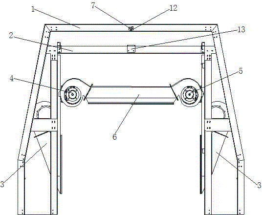
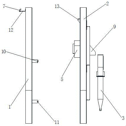
[0029] In a preferred embodiment of the present invention, a drying system of an automatic car washing machine, such as figure 1 and figure 2 As shown, it includes the first gantry 1, the second gantry 2, the top blower assembly, the side blower assembly 3 and the control panel;

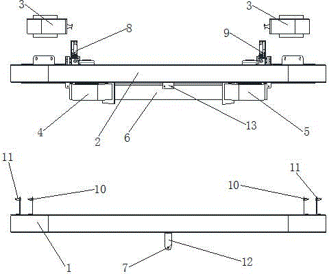
[0030] Such as image 3 and Figure 4 As shown, the above-mentioned top blower assembly includes a first top fan unit 4, a second top fan unit 5, a top fan air duct 6, a distance measuring sensor 7, and a servo motor for driving the first top fan unit 4 and the second top fan unit 5 ( not shown in the figure), and if...


PUM


Abstract

The invention discloses a drying system of an automatic car washing machine. The drying system comprises a first gantry, a second gantry, a top blowing assembly, side blowing assemblies and a control board. The top blowing assembly comprises a first top draught fan set, a second top draught fan set, a top draught fan wind tunnel, a distance measuring sensor and a servo motor; the first top draught fan set is connected with a first top draught fan swinging mechanism, the second top draught fan set is connected with a second top draught fan swinging mechanism, the wind outlets of the first top draught fan set and the second top draught fan set communicate to the left wind inlet and the right wind inlet of the top draught fan wind tunnel, and the wind outlets of the top draught fan wind tunnel follow the shape of the car and have a fixed distance relative to the car body surface; and the servo motor, the distance measuring sensor, the side blowing assemblies and draught fan startup optoelectronic switches arranged on the first gantry are connected with the control board. According to the drying system of the automatic car washing machine, the drying effect is good, the rigid impact, vibration and noise when the top blowing machine assembly is lifted can be avoided, and the service life of electric-mechanical components is favorably prolonged.

Description

technical field [0001] The invention relates to the field of automatic car washing machines, in particular to a drying system of the automatic car washing machine. Background technique [0002] At present, in the existing automatic car washing machines, the combination of top blowing and side blowing is mostly used to dry the car body. Among them, the top blower is controlled by a photoelectric switch. When the photoelectric switch detects that the top surface of the car is The blower goes up, and when the photoelectric switch detects no car, the top blower goes down. It can be seen that this control method will not only make the lifting motor used to lift the top blower start and stop frequently, but also cause the top blower to go up and down frequently. Rigid impact, vibration and noise will have a serious impact on the service life of electrical and mechanical components such as the lifting motor and the top blower; in addition, in the process of drying the car body, the...

Claims


Application Information

Patent Timeline
IPC IPC(8): B60S3/04
Inventor 赵玮吴德全
Owner NANJING LYTON AUTOMATION EQUIP CO LTD
Why Eureka
Try Eureka