Pipe washing and blowing device

A technology for washing and blowing tubes and cleaning sleeves, which is applied in the field of auxiliary production equipment for heat-shrinkable tubes, can solve problems such as poor production continuity, lack of cleaning functions, and single functions, and achieve good cleaning and drying effects, simple structure, and easy connection. firm effect

Inactive Publication Date: 2017-01-04
东莞三联热缩材料有限公司
View PDF9 Cites 0 Cited by
  • Summary
  • Abstract
  • Description
  • Claims
  • Application Information

AI Technical Summary

Problems solved by technology

But this invention has complex structure, single function and lack of cleaning function, troublesome operation, poor production continuity, and needs further improvement

Method used


Image

  • Pipe washing and blowing device
  • Pipe washing and blowing device
  • Pipe washing and blowing device

Examples


Embodiment Construction

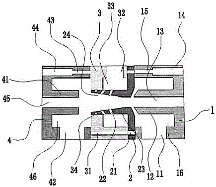
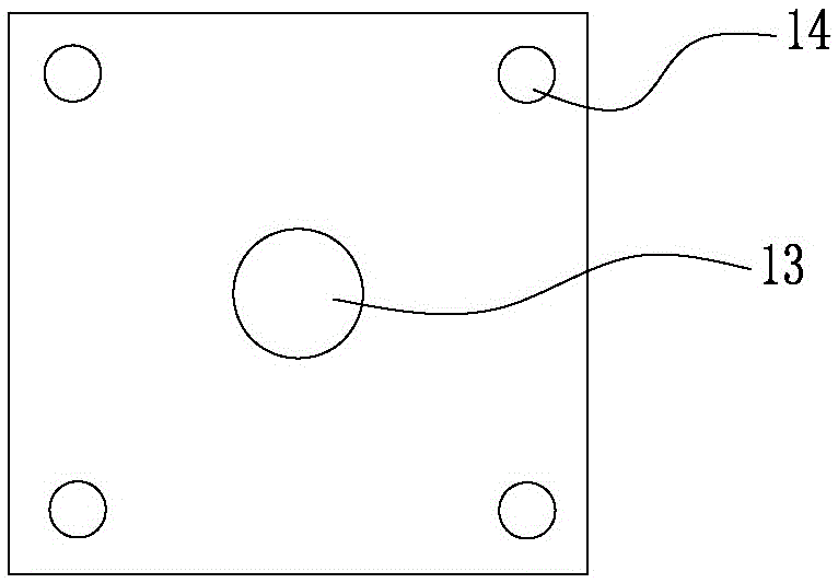
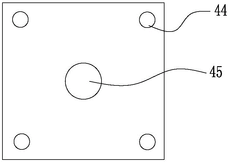
[0017] Such as Figure 1-3 As shown, a pipe washing and blowing device includes a drying sleeve 1, a cleaning sleeve 2, a water injection sleeve 3 and a feeding sleeve 4; Square counterbore 16, the center of the bottom surface of the first square counterbore 16 is formed with a first protruding post 12, the center of the first protruding post 12 is provided with a first through hole 13, the inner side of the first square counterbore 16 is below Air intake holes 11 are provided; four first counterbores 14 are provided at the four corners of the outer end surface of the drying cover 1, and the first through holes 15 are provided in the center of the bottom surface of the first counterbore 14; the drying cover 1 The inner side of the cleaning sleeve 2 is provided with a cleaning cover 2, the shape of the end surface of the cleaning cover 2 is square, and the center of the inner end surface of the cleaning cover 2 is formed with a cleaning column 23, and the center of the cleaning...


PUM


Abstract

The invention relates to a pipe washing and blowing device. The pipe washing and blowing device comprises a blow drying sleeve, a washing sleeve, a water injection sleeve and a feeding sleeve, wherein the washing sleeve is arranged on the inner side of the blow drying sleeve; the center of the inner side end face of the water injection sleeve is provided with a second square counter bore; the center of the bottom surface of the second square counter bore is provided with a third through hole; the front end of a washing post on the washing sleeve is inserted into the third through hole; the feeding sleeve is arranged on the outer side of the water injection sleeve. Water current enters from a water injection hole in the water injection sleeve, passes through current-dividing holes in the washing sleeve, and washes a casing, and wind is injected from an air inlet hole in the blow drying sleeve and is blown towards the surface of the casing through a gap between the blow drying sleeve and the washing sleeve, so that a blow drying effect is achieved.

Description

technical field [0001] The invention relates to the field of heat-shrinkable tube auxiliary production equipment, in particular to a tube washing and blowing device. Background technique [0002] Heat-shrinkable sleeve is a heat-shrinkable packaging material that shrinks when heated. It is widely used in the insulation protection of various wiring harnesses, solder joints, and inductors, and the rust and corrosion protection of metal pipes and rods. After the production of heat-shrinkable sleeves, the outer surface needs to be cleaned and dried. These two steps are usually carried out separately. The operation is cumbersome, the process is lengthy, and the production efficiency is low. [0003] In the prior art, for example, the patent number is 201220142989.6, and the application date is 2012.03.31 "A Heat-shrinkable Tube Blowing Device". Blowing out high-pressure air can completely dry the water on the surface of the heat shrinkable tube. But this invention has complex s...

Claims


Application Information

Patent Timeline
Patent Type & Authority Applications(China)
IPC IPC(8): B08B9/023F26B21/00H01B19/00H01B19/02
CPCB08B9/023B08B2209/02F26B21/00H01B19/00H01B19/02
Inventor 陈鹏李兴光
Owner 东莞三联热缩材料有限公司
Why Eureka
Try Eureka