Rapid air rail transport system

A technology of aerial track and transportation system, applied in the field of transportation, can solve the problems of many intermediate stops, slow transportation speed, high energy consumption of transportation, etc., and achieve the effects of reducing maintenance costs, lowering the requirements for support strength, reducing operating costs and noise

Pending Publication Date: 2017-01-04
戴长虹
View PDF0 Cites 8 Cited by
  • Summary
  • Abstract
  • Description
  • Claims
  • Application Information

AI Technical Summary

Problems solved by technology

[0004] The technical problem to be solved by the present invention is to provide a low-cost project for the shortcomings of the existing transportation system, such as slow transportation speed, long time, many transfer times, many intermediate stops, high transportation energy consumpti

Method used


Image

  • Rapid air rail transport system
  • Rapid air rail transport system
  • Rapid air rail transport system

Examples


Embodiment 1

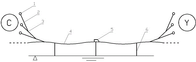
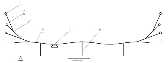
[0044] Example 1: see figure 1 , The rapid air rail transportation system consists of a station 1, a branch track 2, a turnout 3, a main track 4, a rail car 5 and a pillar 6, and also includes a power supply system and a control system.

[0045] The station 1 is set at the beginning or end of the tracks 2 and 4, and the branch track 2 and the branch track 2, and between the branch track 2 and the main track 4 are connected together by a turnout 3, and the turnout 3 is an automatic turnout; the pillar 6 is installed on Below the track 2, 4 along the line, the track 2, 4 is erected in the air through the pillar 6, the rail car 5 runs along the track 2, 4, the track 2, 4 between the adjacent switch 3 is a seamless continuous track, the main The track 4 or the branch track 2 is a straight track or a wave-shaped curved track. The middle section of the curved track hangs down naturally to form a circular arc. The lowest point of the circular arc is suspended in the air and can be fr...

Embodiment 2

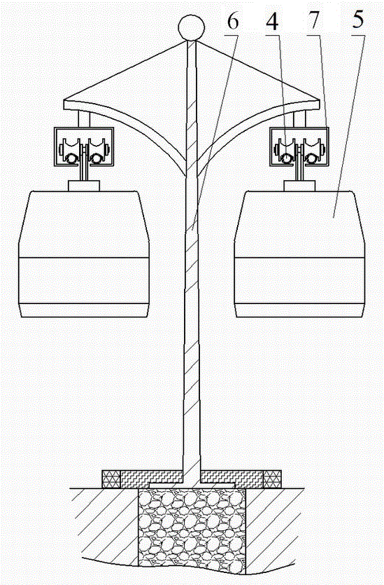
[0064] Example 2: see figure 2 with image 3 , rail car 5 is suspended and travels below track 4, and track 4 is installed in track box 7, and track 4 is erected in the air by track box 7 relying on pillar 6, and track car 5 is suspended in track box 7 below and walks along track 4 below. figure 2 In , there are two track lines, set side by side. Orbit lines can also be set to one, or more lines can be set side by side, and the other parts are basically the same as those in Embodiment 1. The rail car 5 is suspended below the track box 7. The advantage is that the center of gravity of the rail car 5 is low and relatively stable.

Embodiment 3

[0065] Embodiment 3: see Figure 4 with Figure 5 , the track 4 is divided into upper and lower layers, and there are rail cars 5 traveling above and below the track 4. The track 4 above is directly installed on the pillar 6, and the rail car 5 travels above the track 4. Below track 4 is installed in track box 7, and track 4 is erected in the air by track box 7 and relies on pillar 6, and rail car 5 is suspended in track box 7 below and walks along track 4 below. There are two track lines on the upper and lower floors, arranged side by side. The track lines of the upper layer and the lower layer can also be set to one or more. Other settings are basically the same as in Embodiments 1 and 2. Its advantage is that it is set up as two layers to increase the transportation volume, increase the utilization rate of the system, and improve the operating efficiency and travel efficiency.


PUM


Abstract

An intercity or urban rapid air rail transport system comprises stations, supporting columns, rails, turnouts, rail cars, a power supply system and a control system. The rails are erected in the air by means of the supporting columns. The stations are arranged at endpoints or client sides of the rails. The stations, the rails and the turnouts form a rail transport network system like the Internet. The rail cars move along the rails by means of the power supply system and the control system. The intercity or urban rapid air rail transport system can be manufactured at low cost within a short period of time in batches, transport efficiency can be greatly improved, transport cost can be reduced, traffic accidents can be eradicated, and the intercity or urban problems of traffic jam and environment pollution are effectively solved.

Description

technical field [0001] The invention relates to the field of transportation, in particular to a rapid air rail transportation system. Background technique [0002] With the development of the economy and the progress of society, the movement of people and the transportation of goods have become an important part of modern society. Modern transportation tools and systems not only require large transportation volume, good safety and low cost, but also meet the requirements of fast, punctual, Efficient demand. The existing long-distance transportation system mainly includes the three major systems of aviation, railway and land. Air transportation has the advantage of short time in ultra-long-distance transportation, but the cost is relatively expensive, the carrying capacity is relatively limited, and the airport is far away from the urban area; railway transportation In medium and long-distance transportation, it has the advantages of safety, low cost, and large carrying capa...

Claims


Application Information

Patent Timeline
IPC IPC(8): B61B3/02B61B5/02
CPCY02T30/00
Inventor 戴长虹戴启凡
Owner 戴长虹
Why Eureka
Try Eureka