Automatic decoupling mechanism for vehicle coupler

一种车钩、自动的技术,应用在铁路车体部件、铁路车辆联轴器配件、铁路联轴器等方向,能够解决减小侧向力等问题,达到提高稳定性、降低维护成本、提高响应速度和稳定性的效果

Active Publication Date: 2017-01-04
CRRC QINGDAO SIFANG ROLLING STOCK RES INST +1
View PDF4 Cites 14 Cited by
  • Summary
  • Abstract
  • Description
  • Claims
  • Application Information

AI Technical Summary

Problems solved by technology

[0006] The present invention aims at the technical problem that the existing coupler automatic uncoupling device is in the process of coupling the coupler, the extension spring is resisted and it is difficult to drive the knuckle to rotate quickly and lock the coupler, and proposes a device that can reduce the uncoupling of the coupler. The lateral force of the knuckle against the drive unit during the hooking process can also make the tension spring drive the knuckle to rotate quickly and lock the coupler during the coupling process.

Method used


Image

  • Automatic decoupling mechanism for vehicle coupler
  • Automatic decoupling mechanism for vehicle coupler
  • Automatic decoupling mechanism for vehicle coupler

Examples


Embodiment

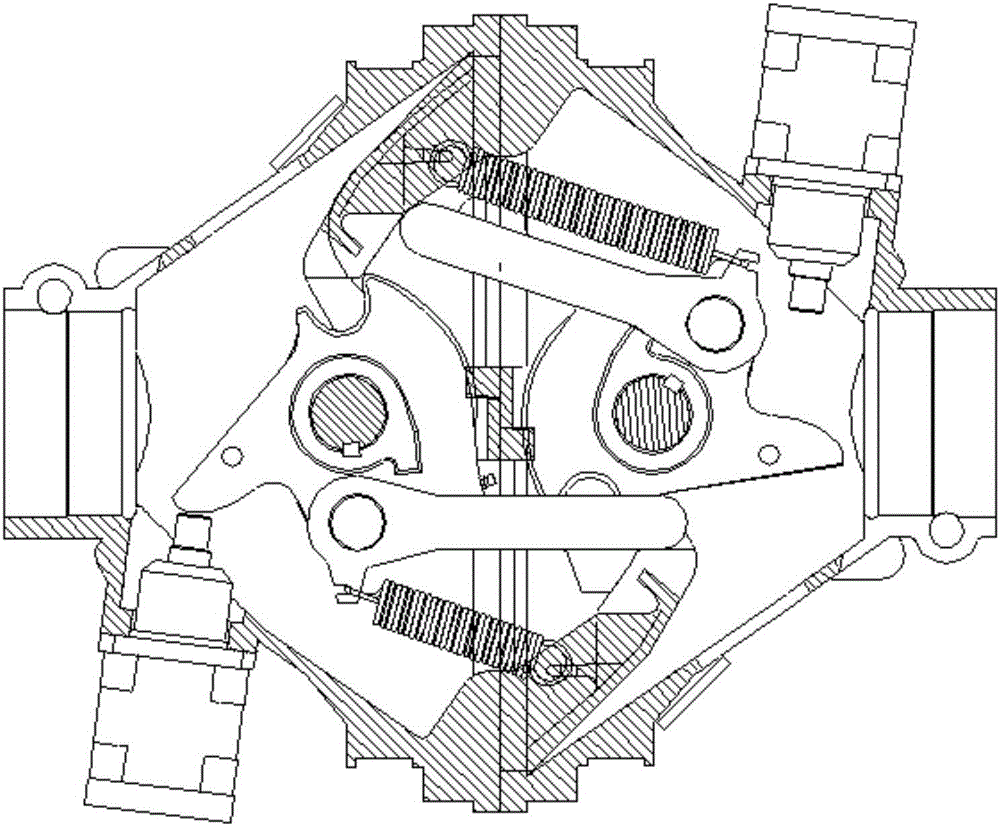
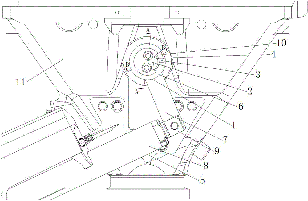
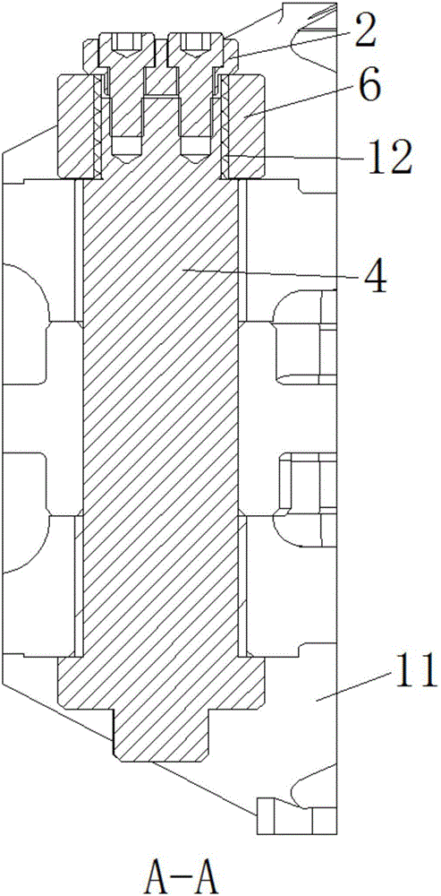
[0032] Example: such as Figure 2 to Figure 4 As shown, a coupler automatic uncoupling mechanism includes a knuckle shaft 4 and a drive unit 5, the drive unit 5 includes a cylinder 8 hinged on the coupler body 11, and a telescopic member 9 that can move axially along the cylinder 8; The coupler automatic uncoupling mechanism also includes a first rotating part 1, a boss 3 and a boss stopper 10, wherein the first rotating part 1 includes a crank 7 hinged to the telescopic part 9, and a rotating part 6 fixedly connected to the crank 7 , the rotating part 6 is sleeved on the knuckle shaft 4; the unidirectional drive of the telescopic member 9 by the drive unit 5 impels the rotating part 6 to drive the knuckle shaft 4 to rotate in one direction through the contact between the boss 3 and the boss stopper 10 , to complete the coupler uncoupling; after the drive unit 5 drives the telescopic member 9 to return, the rotation of the knuckle shaft 4 to complete the coupling of the couple...


PUM


Abstract

The invention provides an automatic decoupling mechanism for a vehicle coupler. The automatic decoupling mechanism comprises a coupler knuckle rotary shaft, a driving unit, a first rotary component, a boss and a boss stopper. The driving unit comprises a cylinder and a telescopic component, the cylinder is hinged onto a coupler, and the telescopic component can axially move along the cylinder; the first rotary component comprises a crank and a rotary portion, the crank is hinged to the telescopic component, and the rotary portion is fixedly connected with the crank and is connected onto the coupler knuckle rotary shaft in a sleeving manner; the telescopic component can be unidirectionally driven by the driving unit, so that the rotary portion can drive the coupler knuckle rotary shaft under the effect of contact between the boss and the boss stopper to unidirectionally rotate, and the vehicle coupler can be decoupled; the coupler knuckle rotary shaft rotates for coupling the vehicle coupler without constraints of the rotary portion after the telescopic component is driven by the driving unit to return. The automatic decoupling mechanism has the advantages that the automatic decoupling mechanism is in an automatic decoupling mode, accordingly, lateral force applied by a coupler knuckle on the driving unit in vehicle coupler decoupling procedures can be reduced, and the coupler knuckle can be driven by tension springs to quickly rotate in vehicle coupler coupling procedures, and the vehicle coupler can be locked.

Description

technical field [0001] The invention belongs to the field of train coupler coupling devices, in particular to a coupler automatic uncoupling mechanism. Background technique [0002] As the basic composition of the coupler coupling device, the uncoupling device plays a role in promoting the rotation of the knuckle tongue mechanism so that the coupler can be disassembled. Existing uncoupling methods include manual uncoupling methods and automatic uncoupling methods, wherein, the existing automatic uncoupling methods of rail vehicles in my country are all pneumatic uncoupling methods. Such as figure 1 As shown, when the pneumatic uncoupling mode is unhooked, the cylinder piston rod stretches out to directly push the knuckle to rotate. However, due to the relatively short surface stroke on the knuckle and the unhooking piston rod, it is difficult to ensure that the force direction of the cylinder piston rod is always along the direction of the piston rod, and then there is a l...

Claims


Application Information

Patent Timeline
Patent Type & Authority Applications(China)
IPC IPC(8): B61G3/14
CPCB61G3/14B61G3/20B61G7/02B61G7/00
Inventor 刘佺杜锦涛李明刚刘继波
Owner CRRC QINGDAO SIFANG ROLLING STOCK RES INST
Why Eureka
Try Eureka