Universal cabinet body of locomotive air braking cabinet

An air brake and cabinet technology, which is applied in the direction of pneumatic brakes, brakes, brake components, etc., can solve the problems of diversification and incompatibility of cabinets, and achieve the effects of avoiding repeated waste, saving materials, and facilitating mass production

Inactive Publication Date: 2017-01-04
CRRC DALIAN CO LTD
View PDF7 Cites 0 Cited by
  • Summary
  • Abstract
  • Description
  • Claims
  • Application Information

AI Technical Summary

Problems solved by technology

[0006] The present invention aims at the deficiency of the existing universal cabinet of the locomotive air brake cabinet, and provides a general cabinet of the locomotive air brake cabinet. By dividing into functional areas, various brake system components can be installed on one cabinet to solve the problem of Solved the problem of diversification and non-universal brake cabinet body

Method used


Image

  • Universal cabinet body of locomotive air braking cabinet

Examples


Embodiment 1

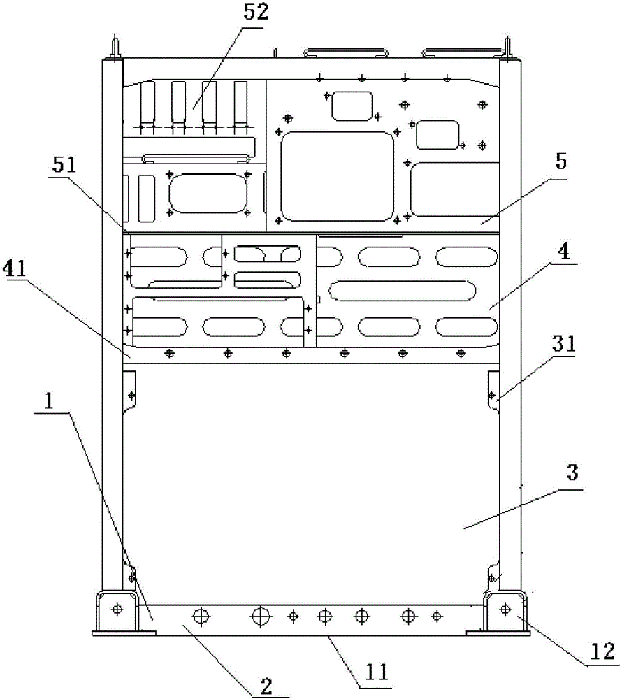
[0021] Embodiment 1: This kind of locomotive air brake cabinet has a general cabinet body. The connecting plate 2 of the base 1 of the cabinet body is provided with an installation interface and a pipeline connection interface for connecting the brake cabinet to the locomotive. The inside of the cabinet body is provided with brake components. Module, microcomputer control component module, auxiliary component module and electrical component module, the four modules are arranged from bottom to top to form four installation layers; the bottom to top arrangement of the installation layers of the four modules is the installation layer 3 of the brake component module , The installation layer of the microcomputer control component module 4, the installation layer of the auxiliary component module, and the installation layer of the electrical component module. Base 1 is made up of base plate 11, underframe 12 and connecting plate 2, and connecting plate 2 is connected with underframe ...

Embodiment 2

[0022] Embodiment 2: This kind of locomotive air brake cabinet has a general cabinet body. The connecting plate 2 of the base 1 of the cabinet body is provided with an installation interface and a pipeline connection interface for connecting the brake cabinet to the locomotive. The inside of the cabinet body is provided with brake components. Modules, microcomputer control component modules, auxiliary component modules and electrical component modules, two of which are installed on one installation layer, and the other two modules are respectively installed on one installation layer, and the three installation layers are arranged from bottom to top. The order of the three installation layers from bottom to top is the installation layer 3 of the brake element module, the installation layer 4 of the microcomputer control component module, and the installation layer 5 of the auxiliary component module and the electrical component module. Base 1 is made up of base plate 11, underfr...


PUM


Abstract

The invention discloses a universal cabinet body of a locomotive air braking cabinet. A connection plate of a base of the cabinet body is provided with an installation interface and a pipeline connection interface, and the braking cabinet and a locomotive are connected through the installation interface and the pipeline connection interface. The cabinet body is internally provided with a braking element module, a microprocessor control part module, an auxiliary part module and an electric element module. The four modules are distributed from bottom to top to form four installation layers, or every two modules are installed on an installation layer, and the two installation layers are distributed from bottom to top, or two modules are installed on an installation layer, the other two modules are installed on another installation layer, and the three installation layers are distributed from bottom to top. The universal cabinet body of the locomotive air braking cabinet solves the problem that a cabinet body of the braking cabinet is diversified, and the cabinet is multifunctional. In the aspect of design, the cabinet body can avoid repeated waste. During production, design and maintenance of tools and jigs can be reduced, and materials and cost are saved. Meanwhile, operation mistakes of workers can be reduced, mass production is convenient, and great assistance is provided for improving product quality.

Description

technical field [0001] The invention relates to a cabinet body, in particular to a cabinet body of a locomotive air brake cabinet, which belongs to the field of locomotives. Background technique [0002] The air brake cabinet for locomotives is mainly used to install brake components, electrical parts, etc. It has been widely used in electric locomotives and diesel locomotives. At present, the brake cabinet cabinets used on locomotives are all the same type of vehicle, and only a single brake system can be installed, so that the brake cabinets are diversified and cannot be used universally. [0003] The brake cabinet cabinet for HXD3 electric locomotive is mainly installed with EPCU components, microcomputers and auxiliary components in the CCBⅡ system. [0004] The brake cabinet cabinet for Dongfeng 10DDA diesel locomotive is mainly installed with JZ-7 brake system integrated air circuit and air cylinder and other components. [0005] The biggest disadvantage of the exis...

Claims


Application Information

Patent Timeline
IPC IPC(8): B61H11/06B60T17/00
CPCB61H11/06B60T17/00
Inventor 王存兵尹逊波赵全福孙健孟贺刘维玉
Owner CRRC DALIAN CO LTD
Why Eureka
Try Eureka