Stacking gripping device

A grasping device and stacking technology, applied in the field of stacking machinery and equipment, can solve the problems of insufficient and reasonable utilization of pallet space, inconvenient disassembly and assembly, and troublesome, so as to achieve the effect of convenient and quick disassembly and assembly, and improve work efficiency.

Inactive Publication Date: 2017-01-04
无锡尚尧智控设备有限公司
View PDF8 Cites 1 Cited by
  • Summary
  • Abstract
  • Description
  • Claims
  • Application Information

AI Technical Summary

Problems solved by technology

[0002] The palletizing and grabbing device in the prior art can only set the height of the barrel, and when the stack reaches the specified position and height, it will be released and just land on the placement point, and they will be lined up one by one. When barrels of different heights are encountered, the stacking needs to be reset position and height; secondly, in the past, the workpieces could only be arranged in the same row in 3*3 or 4*4 through palletizing, so the gap between the barrels and the barrels was large, and the pallet space could not be fully and rationally used; in addition, the gripper under the jaws , The connection method of the jaw base is inconvenient to disassemble and assemble. When encountering workpieces of different sizes, professionals need to disassemble and assemble them to replace them with suitable grippers, which is troublesome.

Method used


Image

  • Stacking gripping device
  • Stacking gripping device
  • Stacking gripping device

Examples


Embodiment Construction

[0030] The technical scheme of the present invention will be described in detail below in conjunction with the accompanying drawings.

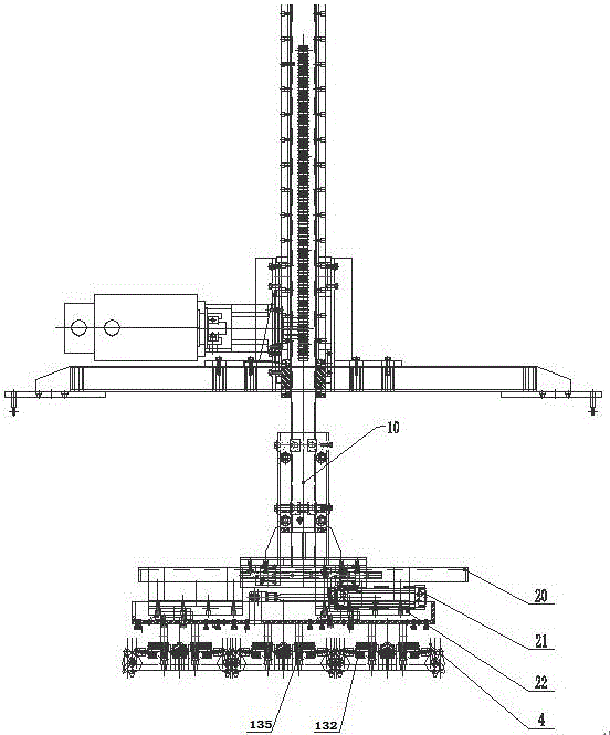
[0031] Such as Figure 3-10 As shown, the present invention discloses a palletizing grabbing device, comprising: a floating lifting mechanism 10; a lifting plate 20 connected to the bottom of the floating lifting mechanism 10; a linear actuator is connected to the lifting plate 20, and the linear actuator is connected to a clamp The jaw fixing seat is provided with a jaw part under the jaw fixing seat.

[0032] Further, the floating lifting mechanism includes a middle sliding rod 110, and a sliding sleeve 120 that is sleeved outside the middle sliding rod 110 and can slide relative to the middle sliding rod 110, between the outer wall surface of the middle sliding rod 110 and the inner wall surface of the sliding sleeve 120 A sliding part is provided.

[0033] Further, the middle sliding bar 110 is a column structure, with front, rear, left ...


PUM


Abstract

The invention discloses a stacking gripping device which comprises a floating lifting mechanism and a lifting plate, wherein the lifting plate is connected with the bottom of the floating lifting mechanism; a linear executing mechanism is connected with the lifting plate; a clamping jaw fixing base is connected with a sliding end of the linear executing mechanism; a clamping jaw part is arranged under the clamping jaw fixing base. The stacking gripping device provided by the invention need not be preset for barrels in different height; when the second layer of workpieces are stacked after stacking of the first layer of workpieces is completed, the barrels are not damaged even if the barrels are in different heights and the workpieces are not damaged even if the middle slide rod continues downward placing (the sliding sleeve of the floating lifting mechanism is moved for an idle stroke for relieving); the operation is convenient; the barrel height needs not to be set each time; the working efficiency is greatly increased.

Description

technical field [0001] The invention relates to the field of palletizing mechanical equipment, in particular to a palletizing grabbing device. Background technique [0002] The palletizing and grabbing device in the prior art can only set the height of the barrel, and when the stack reaches the specified position and height, it will be released and just land on the placement point, and they will be lined up one by one. When barrels of different heights are encountered, the stacking needs to be reset position and height; secondly, in the past, the workpieces could only be arranged in the same row in 3*3 or 4*4 through palletizing, so the gap between the barrels and the barrels was large, and the pallet space could not be fully and rationally used; in addition, the gripper under the jaws , It is inconvenient to disassemble and assemble the connection method of the jaw base. When encountering workpieces with different sizes, it needs professionals to disassemble and replace the...

Claims


Application Information

Patent Timeline
Patent Type & Authority Applications(China)
IPC IPC(8): B65G61/00
CPCB65G61/00
Inventor 郑兴林
Owner 无锡尚尧智控设备有限公司
Why Eureka
Try Eureka