Eureka AIR delivers breakthrough ideas for toughest innovation challenges, trusted by R&D personnel around the world.

Electromechanical lifting system

A lifting system, electromechanical technology, applied in the direction of lifting frame, lifting device, etc., can solve the problems of internal leakage, poor repeat positioning accuracy, pollution, weak wind resistance, etc., achieve high repeat positioning accuracy, ensure normal operation, and occupy space small effect

Inactive Publication Date: 2018-08-07
ANHUI HENGNUO ELECTROMECHANICAL SCI & TECH
View PDF13 Cites 2 Cited by
  • Summary
  • Abstract
  • Description
  • Claims
  • Application Information

AI Technical Summary

Problems solved by technology

[0003] 1) The hydraulic method is used as the driving component, but the hydraulic method has the problems of internal leakage and poor repeat positioning accuracy, and the leakage and pollution of hydraulic oil during the installation and maintenance of hydraulic components
[0004] 2) The scissor brace structure is used as a force-bearing part and a guide part, and its assembly clearance and deformation often fail to meet the technical indicators (theoretical ±10mm sloshing amount is currently rarely met by domestic scissor brace lifting equipment manufacturers)
[0005] 3) Most of the scissor support lifting mechanisms are used in indoor environments, and their wind resistance is weak and their environmental adaptability is poor.
[0006] 4) Large in size and high in quality, the scissor brace needs bearing capacity and guidance, so it is very heavy

Method used


Image

  • Electromechanical lifting system
  • Electromechanical lifting system
  • Electromechanical lifting system

Examples


Embodiment Construction

[0039] The technical solutions in the embodiments of the present invention will be clearly and completely described below in conjunction with the accompanying drawings in the embodiments of the present invention. Obviously, the described embodiments are only some, not all, embodiments of the present invention. Based on the embodiments of the present invention, all other embodiments obtained by persons of ordinary skill in the art without making creative efforts belong to the protection scope of the present invention.

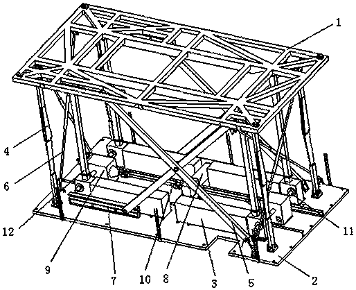
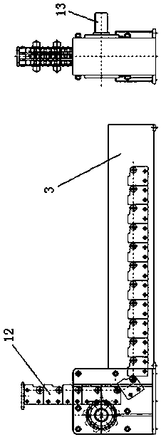
[0040] Such as Figure 1-7 As shown, the electromechanical lifting system includes an upper platform 1, a lower platform 2, a driving motor 8 installed on the lower platform, a flexible chain transmission device installed on the lower platform 2 and the output end is fixedly connected to the upper platform 1, and a flexible chain transmission device installed on the upper platform. Four sets of folding pull rods 4, two sets of scissor braces 5, and four sets of ...


PUM


Abstract

The invention discloses an electromechanical lifting system. The electromechanical lifting system comprises an upper platform, a lower platform, a drive motor installed on the lower platform, a flexible chain transmission device, and four sets of folding pull rods installed between the upper platform and the lower platform, wherein the flexible chain transmission device is installed on the lower platform, and the output end of the flexible chain transmission device is fixedly connected to the upper platform; the four sets of folding pull rods are installed at the four corners of the lifting system correspondingly and arranged in a symmetrical mode; and the drive motor is connected with a flexible chain input shaft of the flexible chain transmission device through a transmission mechanism, the drive motor is connected with a drive piece of the transmission mechanism, and a driven piece of the transmission mechanism is connected with the flexible chain input shaft. Horizontal movement can be directly converted into vertical movement through the flexible chain transmission device, the vertical movement mode is stable, and the repeated positioning accuracy is high. Thus, control over movement of equipment is more accurate, reliable and effective. The compression space of a transmission column device is small, and through combination with an electric speed reducer, the occupied space is small, integral equipment movement is facilitated, and more space dimensions can be provided so that the rigidity of the lifting table system can be improved.

Description

technical field [0001] The invention relates to a lifting system device controlled by electromechanical integration, in particular to a lifting device based on flexible chains, scissor braces, folding pull rods, and diagonal pull rods. Background technique [0002] Most of the scissor support lifting devices used internationally and domestically have the following disadvantages: [0003] 1) The hydraulic method is used as the driving component, but the hydraulic method has the problems of internal leakage and poor repeat positioning accuracy, and the leakage and pollution of hydraulic oil during the installation and maintenance of hydraulic components. [0004] 2) The scissors support structure is used as a force-bearing part and a guide part, and its assembly clearance and deformation often fail to meet the technical indicators (theoretical shaking of ±10mm is currently rarely achieved by domestic scissors support lifting equipment manufacturers). [0005] 3) Most of the s...

Claims


Application Information

Patent Timeline
Patent Type & Authority Patents(China)
IPC IPC(8): B66F7/06B66F7/02B66F7/28
CPCB66F7/02B66F7/065B66F7/28
Inventor 王庆虎张太林陈曦陈世杰
Owner ANHUI HENGNUO ELECTROMECHANICAL SCI & TECH
Why Eureka
Eureka Blog
Learn More