Steel sheet pile dewatering well structure

A technology for steel sheet piles and dewatering wells, which is applied to sheet pile walls, foundation structure engineering, construction, etc., can solve the problems of poor precipitation effect, easy collapse, and high cost of dewatering wells, so as to reduce the number of constructions, reduce construction costs, and improve precipitation. The effect of efficiency

Active Publication Date: 2018-12-18
CHINA CONSTR EIGHT ENG DIV CORP LTD
View PDF6 Cites 0 Cited by
  • Summary
  • Abstract
  • Description
  • Claims
  • Application Information

AI Technical Summary

Problems solved by technology

[0004] In view of the above situation, the present invention provides a steel sheet pile dewatering well structure, by setting adjustable number and continuous splicing steel sheet piles in the foundation pit, and setting H-shaped steel beams and supporting steel pipes inside the steel sheet piles to solve the cost of traditional dewatering wells Higher, easy to collapse, poor precipitation effect and other problems, to achieve the purpose of taking into account the low construction cost of the precipitation well and the high-efficiency precipitation

Method used


Image

  • Steel sheet pile dewatering well structure
  • Steel sheet pile dewatering well structure
  • Steel sheet pile dewatering well structure

Examples


Embodiment Construction

[0031] In order to facilitate the understanding of the present invention, the following will be described in conjunction with the accompanying drawings and embodiments.

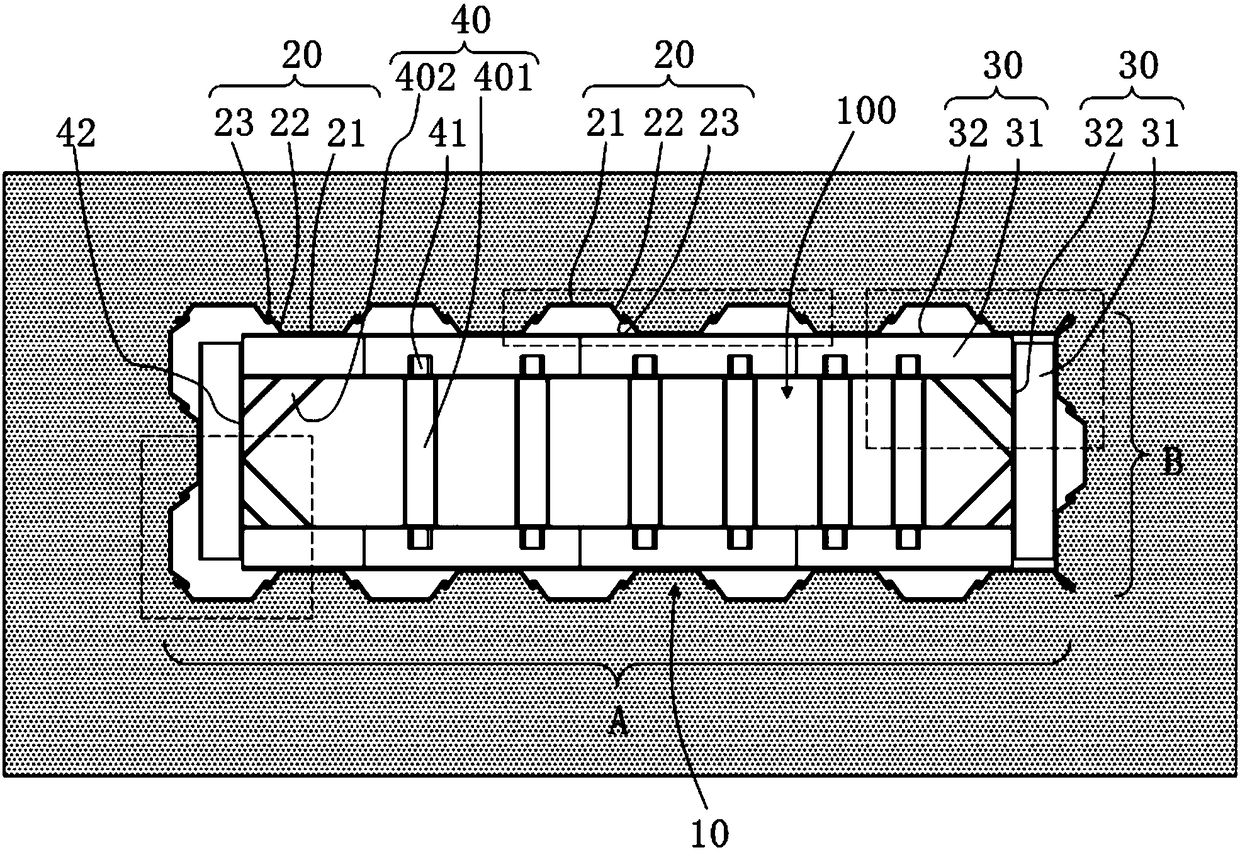
[0032] see Figure 1 to Figure 10 , The present invention provides a combined steel structure dewatering well 100 structure, which is arranged in a foundation pit 10, and the foundation pit 10 has a ground 11, a soil layer 12 and a rock layer 13 in sequence from top to bottom. The present invention is used to penetrate in the soil layer 12 and be arranged on the rock layer 13 .

[0033] The structure of the steel sheet pile dewatering well 100 of the present invention specifically includes a steel sheet pile 20, an H-shaped steel beam 30 and a supporting steel pipe 40; wherein:

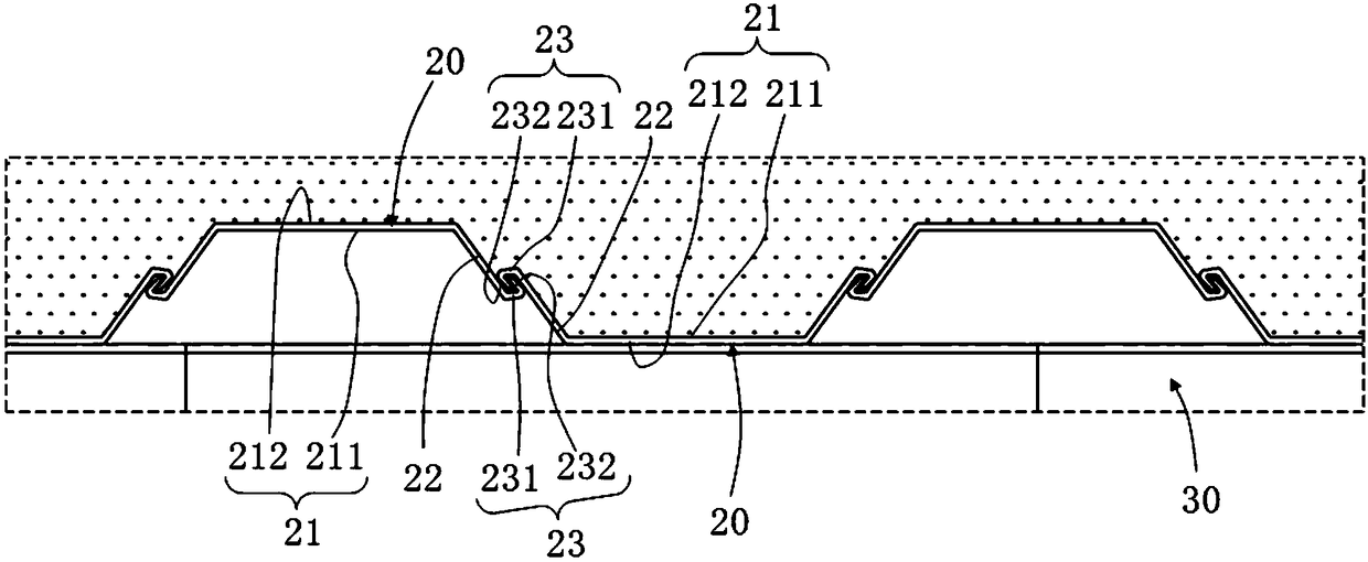
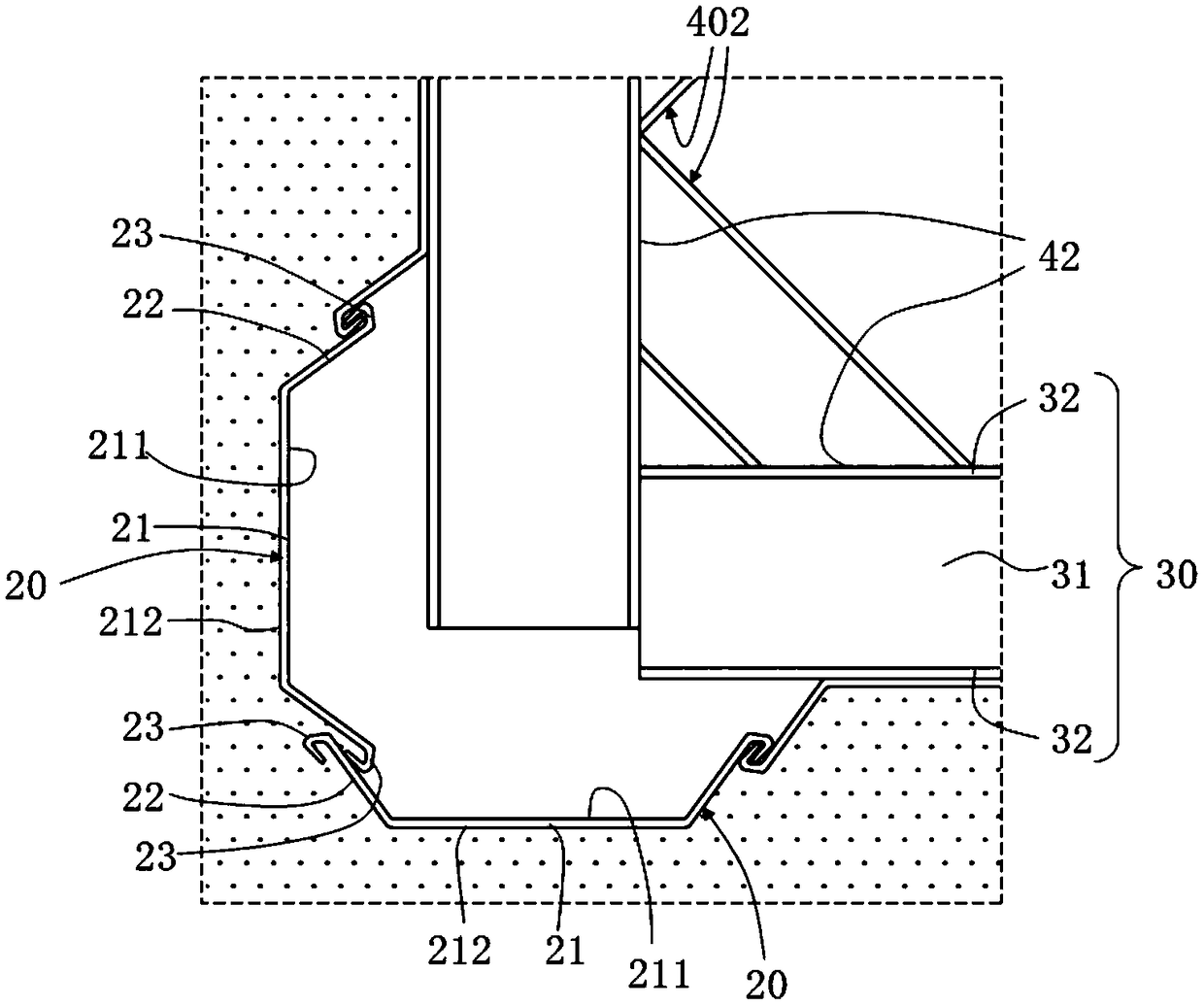
[0034] Such as Figure 5 , Image 6 As shown, the steel sheet pile 20 has a plurality of pieces that can be continuously spliced ​​and arranged on the pit wall of the foundation pit 10; each of the steel sheet piles 20 has a main ...


PUM


Abstract

The invention provides a steel plate pile precipitation well structure. The steel plate pile precipitation well structure comprises steel plate piles respectively formed with two hook-holding portions on two opposite sides, H-shaped steel beams transversely supported on the inner sides of the steel plate piles in the splicing direction of the steel plate piles, and supporting steel pipes connected among the H-steel beams to uniformly support the H-steel beams, wherein the steel plate piles are continuously and vertically arranged in a foundation pit through the hook-holding portions in a spliced mode. Therefore, the problems of higher cost, easy collapse, poor precipitation effect and the like of a traditional precipitation well are solved and the purposes of considering the low construction cost of the traditional precipitation well and efficient precipitation are achieved by arranging the continuously spliced steel plate piles adjustable in number in the foundation pit and arranging the H-steel beams and the supporting steel pipes on the inner sides of the steel plate piles.

Description

technical field [0001] The invention relates to the technical field of water wells, in particular to a dewatering well structure. Background technique [0002] The precipitation well is a well drilled for lowering the groundwater level. After drilling, the water pump is put into the groundwater to reduce the groundwater level. It is one of the measures to ensure the smooth construction of the foundation pit. Traditional precipitation wells are mostly tube well structures. [0003] However, traditional tube wells are only suitable for installation in non-rock formations. Not only do they have high requirements for the construction environment, but the overall structural strength is also poor, and they are prone to collapse. Moreover, the diameter of the tube well is small. In order to meet the design dewatering requirements, generally The efficiency of precipitation can only be improved by building multiple precipitation wells. Therefore, traditional precipitation wells nee...

Claims


Application Information

Patent Timeline
Patent Type & Authority Patents(China)
IPC IPC(8): E02D19/10E02D5/04E02D5/08
CPCE02D5/04E02D5/08E02D19/10E02D2300/0029E02D2300/0032
Inventor 袁光辉刘勇邹家撇陈树龙何嘉骏诸葛仲彦杨冬常龙毛黎明袁泉张威
Owner CHINA CONSTR EIGHT ENG DIV CORP LTD
Why Eureka
Try Eureka