Foundation pit dewatering construction method in stratum containing laminar flow supply source

A construction method and technology for foundation pits, which are applied in infrastructure engineering, waterway systems, water supply devices, etc., can solve problems such as groundwater waste and low water inflow, and achieve the goal of reducing construction costs, reducing construction workload, and improving construction efficiency. Effect

Active Publication Date: 2022-03-29
CHINA CONSTR FIFTH ENG DIV CORP LTD
View PDF6 Cites 1 Cited by
  • Summary
  • Abstract
  • Description
  • Claims
  • Application Information

AI Technical Summary

Problems solved by technology

[0004] The above-mentioned prior art is proposed when the tube well dewatering system cannot meet the drainage demand in order to cope with the sudden rise of the groundwater level
In addition, in the prior art, there is also a method in which tube wells and sump pits are coordinated for dewatering during the entire construction process. However, in actual work, the tube wells of this type of drainage system work from the beginning to the end. For the foundation pit in the formation, the water inflow is not large in the part far away from the laminar flow supply source. If the tube well is opened in the whole process, a large amount of groundwater will be pumped out, resulting in waste of groundwater

Method used


Image

  • Foundation pit dewatering construction method in stratum containing laminar flow supply source
  • Foundation pit dewatering construction method in stratum containing laminar flow supply source
  • Foundation pit dewatering construction method in stratum containing laminar flow supply source

Examples


specific Embodiment 1

[0041] Concrete embodiment 1 of the foundation pit dewatering construction method in the stratum containing the laminar flow supply source provided by the present invention, in the present embodiment, take excavating a deep foundation pit in the pebble formation containing the laminar flow supply source as an example for the present invention The construction method of foundation pit dewatering in strata containing laminar flow recharge source is introduced, as follows:

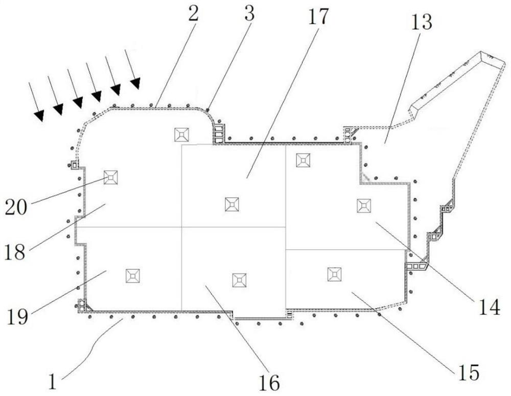
[0042] Such as figure 1 As shown in Fig. 1 , enclosure piles 2 are arranged on the periphery of the base level of the foundation pit 1 below the groundwater level. Before excavation, a tube well drainage system consisting of tube wells 3 is installed on the outside of the enclosure piles 2. The number of tube wells 3 is calculated Methods as below:

[0043] First calculate the total water inflow Q of foundation pit 1:

[0044] Q=π×k×(2H-s d )×s d / ln(1+R / r 0 )

[0045] Calculation of single well water o...

specific Embodiment 6

[0076] The specific embodiment 6 of the foundation pit dewatering construction method in the formation containing the laminar flow supply source provided by the present invention is mainly different from the embodiment 1 in that the areas of each excavation section in the embodiment 1 are equal or close to each other. In the example, the area of ​​each excavation section is different.


PUM


Abstract

The invention belongs to the field of foundation pit dewatering excavation construction, and particularly relates to a foundation pit dewatering construction method in a stratum containing a laminar flow supply source. According to the method, a foundation pit is excavated in a layered mode, and when an aquifer is excavated, the aquifer is divided into two or more excavation sections for dewatering and excavation; according to the stratum water replenishing speed of each excavation section, the following modes are adopted for dewatering the corresponding excavation section: (1) firstly, tube well pre-dewatering is adopted, and then water collection pit open drainage continues to drain water for dewatering; in the second mode, tube well pre-precipitation is adopted firstly, before tube well pre-precipitation is finished, water collecting pit open drainage is adopted for collaborative precipitation, and after collaborative setting time is finished, water collecting pit open drainage is adopted for precipitation; (3) tube well pre-precipitation is adopted firstly, before tube well pre-precipitation is finished, water collection pit open drainage collaborative precipitation is adopted, and tube well precipitation at least lasts until excavation of the excavation section is completed; and the stratum water replenishing speeds of the excavation sections corresponding to the mode 1, the mode 2 and the mode 3 are sequentially increased, and low-cost and environment-friendly rainfall in the construction period is achieved.

Description

technical field [0001] The invention belongs to the field of foundation pit dewatering excavation construction, and in particular relates to a foundation pit dewatering construction method in a stratum containing a laminar flow supply source. Background technique [0002] When the foundation pit is excavated to a certain depth, groundwater will be encountered. At this time, precipitation treatment is required, especially when digging deep foundation pits in strata containing laminar flow recharge sources, such as digging deep foundation pits in pebble strata containing laminar flow recharge sources. The permeability coefficient of the pit and pebble formation is relatively large, and after excavation to the pebble formation, there will be a large amount of water inflow in the direction of the laminar flow recharge source, and precipitation treatment must be carried out. [0003] The commonly used dewatering methods in the prior art include the tube well pumping type and the ...

Claims


Application Information

Patent Timeline
Patent Type & Authority Applications(China)
IPC IPC(8): E02D19/06E02D19/10E03F3/04
CPCE02D19/06E02D19/10E03F3/046
Inventor 韩晓冬赵艳恒李民举代东亮张龙刘铭王智奇党飞王嘎鑫马建军王举韩书娟赵耀威刘瑞冰柳正
Owner CHINA CONSTR FIFTH ENG DIV CORP LTD
Why Eureka
Try Eureka