A masonry method for prestressed mortar-free block retaining wall in agglomerate mode
A prestressed and retaining wall technology, applied in construction, artificial islands, infrastructure engineering, etc., can solve problems such as limited use of dry retaining walls, excavation of reinforced retaining walls, and no soil removal allowed , to achieve the effect of local maintenance, exempt from excavation work, and facilitate the release of prestressing
- Summary
- Abstract
- Description
- Claims
- Application Information
AI Technical Summary
Problems solved by technology
Method used
Image
Examples
Embodiment 1
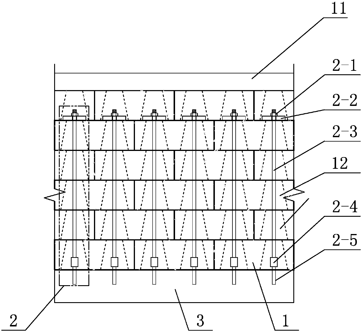
[0039] Example 1: Combining Figure 1 to Figure 15Describe this embodiment, this embodiment includes a plurality of concrete retaining blocks 1 and a plurality of prestressed positioning connectors 2, a plurality of concrete retaining blocks 1 are arranged in sequence to form a retaining wall body, the retaining wall body The top is provided with a top layer 11, the bottom of the retaining wall body is provided with a base layer 3, and a plurality of prestressed positioning connectors 2 are evenly distributed in the retaining wall body;
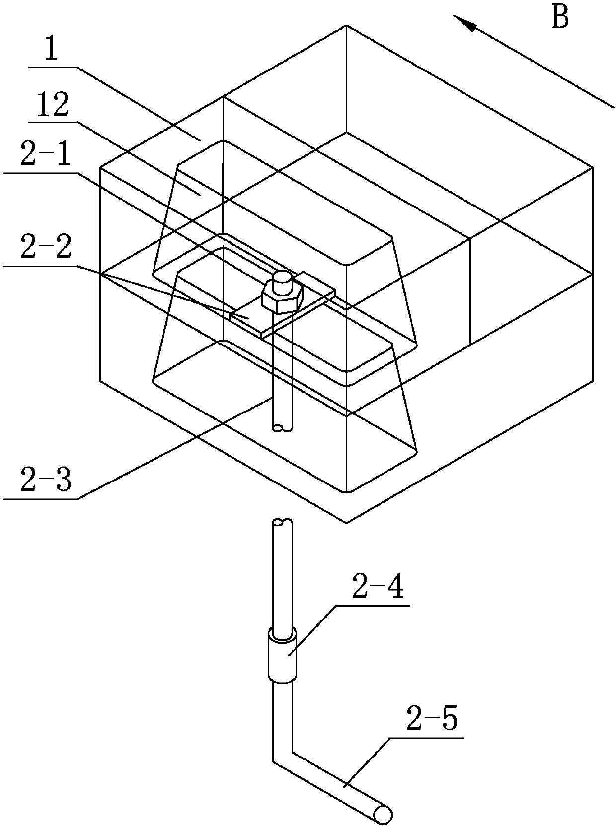
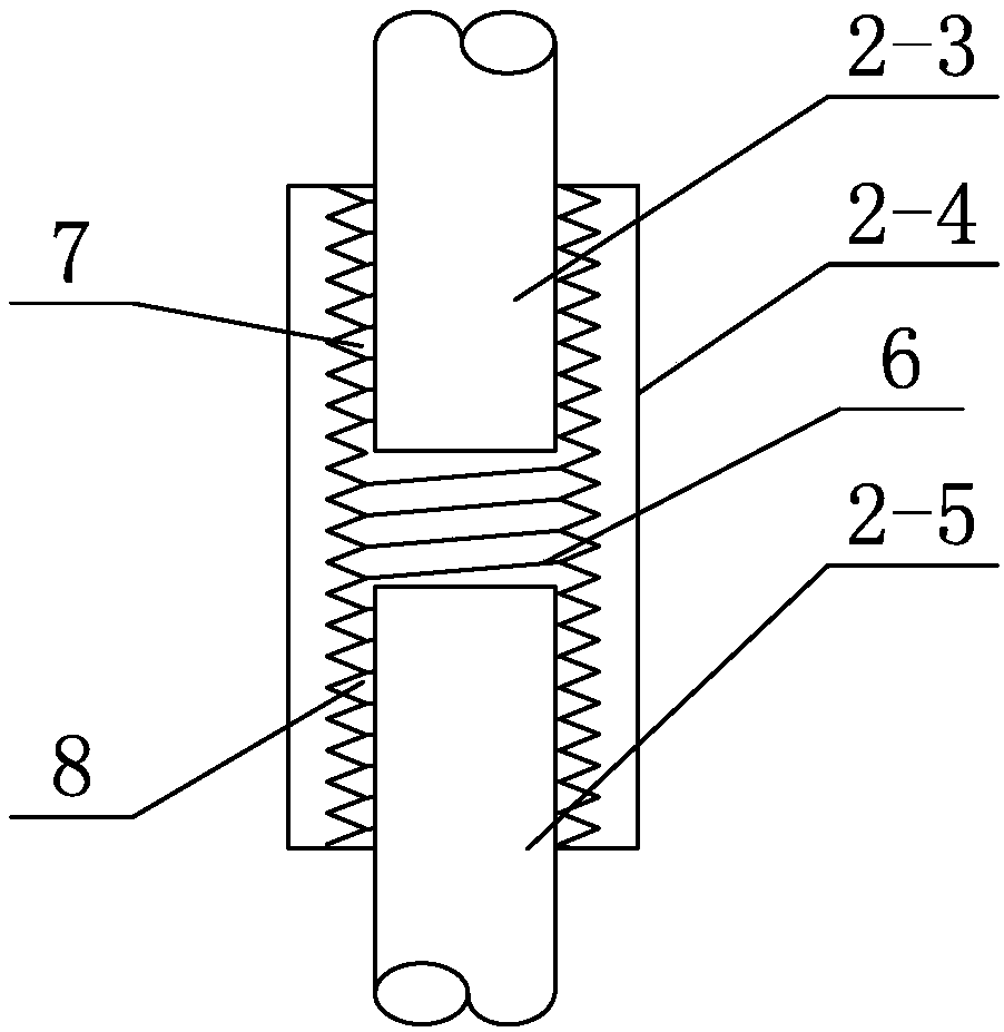
[0040] Each prestressed positioning connector 2 comprises a nut 2-1, a cover plate 2-2, a prestressed steel bar 2-3, a steel bar connector 2-4 and an embedded steel bar 2-5 for applying prestressed force, and the cover plate 2- 2 Horizontally arranged between the side rib 13 and the middle rib 14 of one concrete retaining block 1 among the multiple concrete retaining blocks 1, the tops of the prestressed steel bars 2-3 pass through the concre...
Embodiment 2
[0044] Embodiment 2: In this embodiment, a plurality of concrete retaining blocks 1 are arranged in a staggered manner to form a retaining wall body. Staggered masonry is staggered masonry.
[0045] The concrete retaining block 1 in this embodiment is a new type of retaining block, and its size and shape can be varied according to user needs and site conditions. Two holes 12 are processed in the concrete retaining block 1. The hole 12 is a hole with a wide top and a narrow bottom. During laying, the difference between the top surface and the bottom surface is used to place the prestressed cover plate 2-2. The width of the side rib 13 of the hole 12 is half of the width of the middle rib 14. When the staggered joint is built, the hole 12 can be penetrated vertically, and the two adjacent concrete retaining blocks 1 in the vertical direction can realize the hole alignment. The effect of the hole is to facilitate the passage of prestressed steel bars 2-3.
[0046] In this embo...
Embodiment 3
[0048] Embodiment 3: The plurality of concrete retaining blocks 1 in the retaining wall body described in this embodiment that are in contact with the top layer 11 are the topmost block layer 4, and each concrete retaining block in the topmost block layer 4 The soil block 1 is connected to its adjacent concrete retaining block 1 through a plurality of pins 9, and the plurality of concrete retaining blocks 1 in contact with the topmost block layer 4 in the retaining wall body are the second Each concrete retaining block 1 in the top block layer 5 and the second top block layer 5 is connected to other concrete retaining blocks 1 on the same vertical line through a prestressed positioning connector 2 .
[0049] In this embodiment, the topmost block layer 4 adopts multiple pins 9 to realize the connection with the second top block layer 5, which not only realizes the structural requirements, but also meets the mechanical characteristics and needs of the actual retaining soil. Othe...
PUM
 Abstract
Description
Claims
Application Information
 - R&D
- Intellectual Property
- Life Sciences
- Materials
- Tech Scout
- Unparalleled Data Quality
- Higher Quality Content
- 60% Fewer Hallucinations
Browse by: Latest US Patents, China's latest patents, Technical Efficacy Thesaurus, Application Domain, Technology Topic, Popular Technical Reports.
© 2025 PatSnap. All rights reserved.Legal|Privacy policy|Modern Slavery Act Transparency Statement|Sitemap|About US| Contact US: help@patsnap.com


