Assembly type laminated slab installing and locating method

An installation method and a technology of laminated slabs, which are applied to floors, building components, buildings, etc., can solve the problems of not being able to eliminate cracks in reinforced concrete slabs, negative impacts on safety at cracks, and increased consumption of steel bars, achieving high rigidity and increased consumption of steel bars , the effect of shortening the construction period

Active Publication Date: 2017-01-04
CHENGDU NO 4 CONSTR ENG
View PDF6 Cites 12 Cited by
  • Summary
  • Abstract
  • Description
  • Claims
  • Application Information

AI Technical Summary

Problems solved by technology

[0004] The purpose of the present invention is to overcome the structural system of the existing buildings existing in the prior art and adopts cast-in-place reinforced concrete, but this adopts the mode of whole cast-in-place can't prevent cracks from appearing on the reinforced concrete slab, beam or column, although these Cracks do not completely affect the stability and safety of the overall structure of the building, but consumers may worry about the above-mentioned shortcomings of the negative impact on the safety of cracks. A method for installing and positioning prefabricated...

Method used


Image

  • Assembly type laminated slab installing and locating method
  • Assembly type laminated slab installing and locating method
  • Assembly type laminated slab installing and locating method

Examples


Embodiment 1

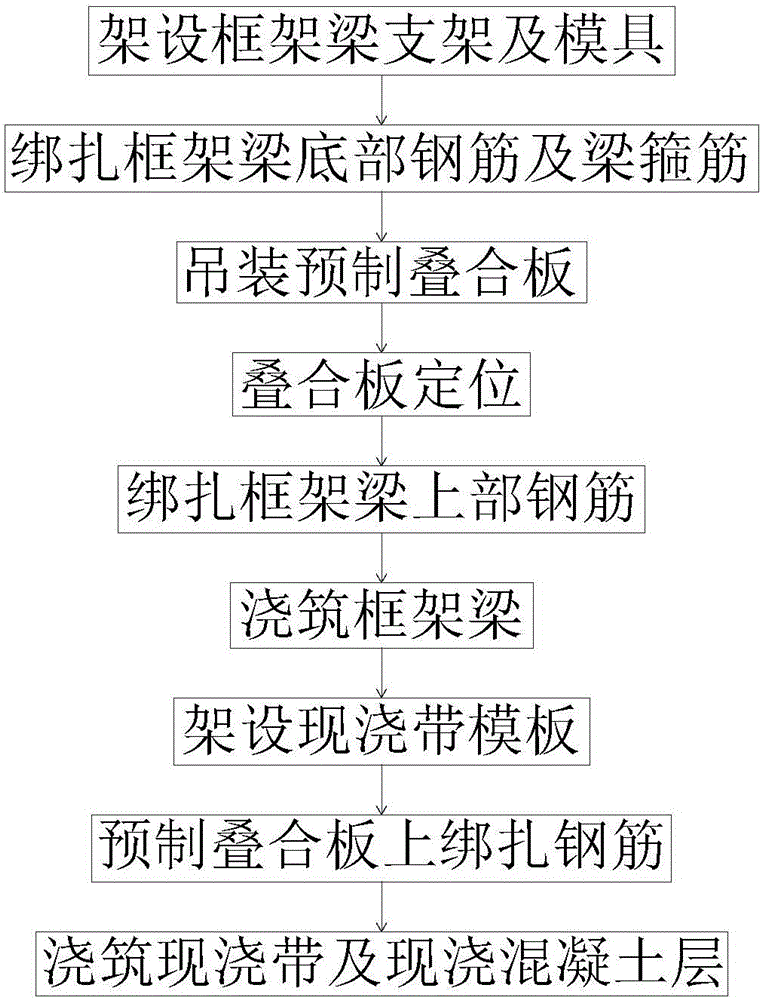
[0075] Such as Figure 1-8 As shown, a method for installing a prefabricated laminated panel according to the present invention includes the following steps:

[0076] A. Erection of frame beam 4 brackets and molds from the lower floor;

[0077] B, binding the bottom steel bar 42 and the beam stirrup 43 of the frame beam 4;

[0078] C, hoisting all prefabricated laminated panels 3 so that their ends are set at the midline of the frame beam 4;

[0079] D, positioning all the prefabricated laminated panels 3;

[0080] E, binding the upper reinforcement 41 of the frame beam 4;

[0081] F, pouring the frame beam 4;

[0082] G. Formwork 9 is set below the gap area between two adjacent prefabricated laminated panels 3, and the template 9 is supported by a support system 93 erected on the lower floor. The side walls of the two prefabricated laminated panels 3 are connected to The template 9 forms a cast-in-place belt 8;

[0083] H, binding the negative moment reinforcement and s...

Embodiment 2

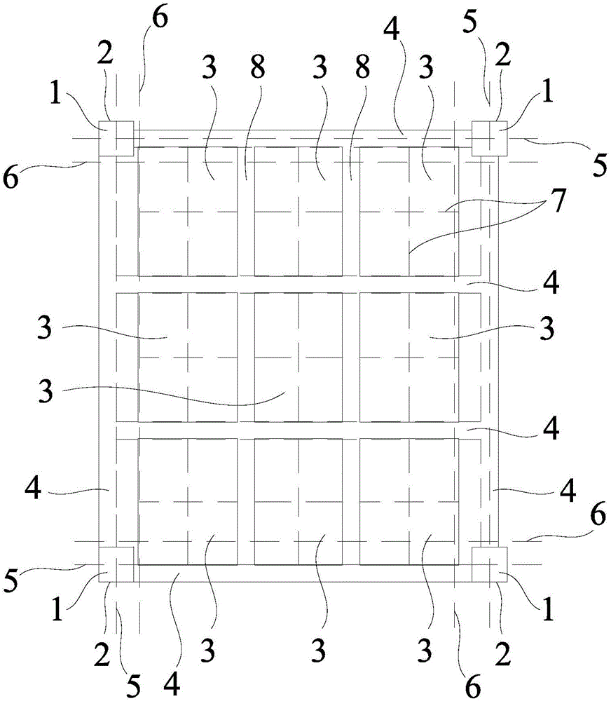
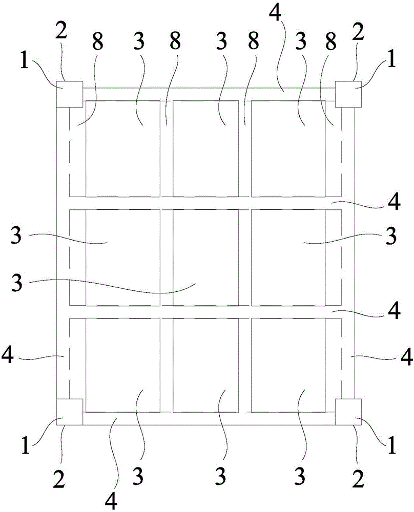
[0105] Such as Figure 2-9 As shown, a method for locating assembled laminated panels according to the present invention includes the following steps:

[0106] 1. Install the positioning stirrups 2 with a diameter of 20mm on all the frame column steel bars 11 on each floor;

[0107] II. Lead each reference control axis 5 on the ground floor to each floor, and mark the position of each axis 5 on the corresponding positioning stirrup 2;

[0108] III. Release all the axes 5, and check the distance and angle between each axis 5 on all frame columns 1 to meet the design requirements;

[0109] Ⅳ. Pop out its two centerlines 7 on each prefabricated panel 3 with a number;

[0110] V. According to the positional relationship between each center line 7 and the corresponding axis 5 in the design requirements, each center line 7 is bounced on the corresponding frame beam 4 side formwork;

[0111] VI. According to the design requirements, install the prefabricated panels 3 with correspo...


PUM


Abstract

The invention discloses an assembly type laminated slab installing and locating method. The assembly type laminated slab installing and locating method comprises the following steps that A, a frame beam support and a mold are erected; B, bottom rebars and beam stirrups of a frame beam are bound; C, all prefabricated laminated slabs are lifted; D, all the prefabricated laminated slabs are located; E, upper rebars of the frame beam are bound; F, the frame beam is subjected to pouring; G, a cast-in-place belt template is erected; H, rebars are bound on all the prefabricated laminated slabs; and I, cast-in-place belts and cast-in-place concrete layers are subjected to pouring. Through the assembly type laminated slab installing method, many prefabricated laminated slabs are installed on the designed and set frame beam and are located, and then the cast-in-place concrete layers are formed on the prefabricated laminated slabs so as to form the complete laminated slabs. The laminated slabs installed through the installing method have the integrality of cast-in-place reinforced concrete slabs and have the advantages that the rigidity is high, the crack resistance is good, rebar consumption is not increased, templates are saved, and the construction period of the whole project is shortened, and the safety is high.

Description

technical field [0001] The invention relates to a building construction method, in particular to a method for installing and locating assembled laminated panels. Background technique [0002] With the continuous development of our country's economy and the improvement of people's living standards, the construction of infrastructure, especially buildings, has become larger and larger. In order to improve the plane stiffness, seismic performance and anti-leakage performance of buildings, existing buildings The structural system adopts cast-in-place reinforced concrete, but this method of integral cast-in-place cannot eliminate cracks on reinforced concrete slabs, beams or columns. Although these cracks do not completely affect the stability and safety of the overall structure of the building, they are important to Consumers will worry about the negative impact of the safety of cracks. At the same time, cast-in-place reinforced concrete slabs need to build a large number of sup...

Claims


Application Information

Patent Timeline
IPC IPC(8): E04B5/17
CPCE04B5/17
Inventor 谢惠庆欧定文李熊飞廖忠伦刘小刚刘琴杨艳申毅林伦俊贾鹏坤罗佳王辉叶青成赵从举黄程靖冯宇
Owner CHENGDU NO 4 CONSTR ENG
Why Eureka
Try Eureka