Perimeter security protection net and perimeter security protection method

A safety protection and security technology, applied in the direction of fences, building types, buildings, etc., can solve the problems of high cost of electrostatic induction, high maintenance cost, poor practicability, etc., to achieve the effect of not easy to find or avoid, improve reliability, and improve accuracy

Active Publication Date: 2018-09-07
NEW SINGULARITY INT TECHN DEV
View PDF8 Cites 0 Cited by
  • Summary
  • Abstract
  • Description
  • Claims
  • Application Information

AI Technical Summary

Problems solved by technology

Among them, the protection level of infrared radiation and microwave radiation is low, and deliberate intruders are easy to cross or avoid, and are also easily affected by environmental factors such as terrain conditions or harsh weather; vibrating cables / optical fibers are greatly affected by the outside world, pedestrians or passing vehicles, etc. The vibration generated can easily cause false alarms; leaking cables are expensive, complex construction, and thunderstorms are prone to false alarms and cannot accurately locate the intrusion location; electronic fences / grids are harmful to people; electrostatic induction is too expensive
[0004] It can be seen that the traditional perimeter security protection system has a low protection level, is easily affected by the external environment (terrain, bad weather, etc.) low repair ability
This leads to problems such as low accuracy, low sensitivity, high maintenance cost, and poor practicability of the perimeter security protection system.

Method used


Image

  • Perimeter security protection net and perimeter security protection method
  • Perimeter security protection net and perimeter security protection method
  • Perimeter security protection net and perimeter security protection method

Examples


Embodiment 1

[0060] use figure 2 Any one of the shown security cables 1 to 5 forms the detection sensing field of the perimeter security protection area. The receiving / transmitting state of the detector in the one security cable is set so that the detection signal radiation field forms a dense detection sensing field around the security cable.

[0061] The detectors in a security cable include transmitting detectors and receiving detectors. The transmitting detectors and receiving detectors are spaced apart, and the ratio of the number of transmitting detectors to receiving detectors is a preset ratio, which is less than or equal to 1 . For example, the ratio of transmitting detectors to receiving detectors can be 1:1, or less than 1, that is, the number of transmitting detectors and receiving detectors set in a security cable are the same, or the number of transmitting detectors is smaller than that of receiving detectors. Quantity.

[0062] The transmitting detector and the receiving detec...

Embodiment 2

[0072] use figure 2 The two security cables in the two security cables form a detection sensing field. Specifically, one of the two security cables transmits detection signals and the other receives detection signals. The two security cables receive and send detection signals to form multiple detection signal radiation fields, multiple detection signals The radiation field is cross-covered to form a continuous and seamless detection sensing field.

[0073] Among them, the two security cables can divide the work to send and receive detection signals, and can also switch the roles of sending and receiving at any time. Assuming that the two security cables are A and B, you can set the security cable A as the transmitting cable, that is, the detectors in the security cable A are set as transmitting detectors; the security cable B is the receiving cable, that is, the detectors in the security cable B are all Set as a receiving detector; you can also switch the transceiver status of s...

Embodiment 3

[0086] Three security cables are used to form a detection sensing field. The three security cables can form a variety of combinations of sending and receiving signals to form a larger security protection area. For example, one security cable transmits detection signals and the other two security cables receive detection signals, or two security cables transmit detection signals and the other security cable receives detection signals.

[0087] (1) Three security cables form a triangular combination

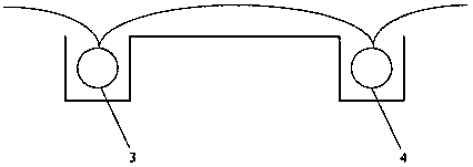
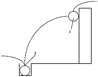
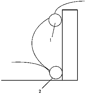
[0088] For example, using figure 2 In the security cables 1, 2 and 3, two security cables 1 and 2 are hung on the fence, and the other security cable 3 is buried below the ground. Among them, 2 can be set as a launch cable, and 1 and 3 can be set as The receiving cable can detect the process of intruding objects approaching the fence and overturning the wall.

[0089] Such as Figure 7 As shown, the area between security cables 2 and 3 is set as a warning area. Similarly, the area betwe...


PUM


Abstract

The invention discloses a perimeter safety protection net and a perimeter safety protection method. A safety protection cable is arranged along the protection border of a safety protection area. A detector is arranged in the safety protection cable and can receive/send a detection signal. A detection perceptual field is formed by the detection signal sent by the detector on the periphery of the safety protection cable. When a person or object invades the detection perceptual field, the detection signal in the detection perceptual field is fluctuated, and whether an invader exists or not is determined according to fluctuation of the detection signal. The safety protection cable can be hung on a wall, buried under the ground or suspended and can be suitable for various complex terrains. After being buried under the ground, the safety protection cable has very high concealment and is not easy to be found or evaded by invasion personnel. The detector is integrated in the safety protection cable and has the advantages of being high in stability and not easy to be affected by various environmental and climatic factors. Moreover, the protection net can filter out the influences of the interference factors to the detection result more effectively, and the accuracy of detecting the invader is improved.

Description

Technical field [0001] The invention relates to the technical field of perimeter security, in particular to a perimeter safety protection net and a perimeter safety protection method. Background technique [0002] Perimeter security protection system refers to a defense system that guards against the boundary of a certain area or alarms when the boundary is invaded by foreign objects. The perimeter security protection system has gradually developed from the initial purely physical precautions (for example, fences, walls) to the current comprehensive perimeter security precaution system that combines physical defense, technical defense, and civil defense. [0003] The existing perimeter security protection system is roughly divided into: infrared radio, microwave radio, leaky cable, vibrating cable / optical fiber, electronic fence / grid, electrostatic induction and other perimeter alarm systems. Among them, infrared radiation and microwave radiation have low protection levels. Intent...

Claims


Application Information

Patent Timeline
Patent Type & Authority Patents(China)
IPC IPC(8): E04H17/00
Inventor 邵起明郑明吉阴子阳
Owner NEW SINGULARITY INT TECHN DEV
Why Eureka
Try Eureka