Wellhead large-drift diameter continuous ball catcher and control method thereof

A large-diameter, pressure-suppressing ball technology, which is applied in earthwork drilling, wellbore/well components, production fluids, etc., can solve the problem that the lateral flange of the gas tree has a small diameter and it is difficult to pass a large-diameter pressure-suppressing ball, reducing The number of catching balls and other issues can be met to meet the requirements of safety production, efficiently recycle pressured balls, and improve the effect of catching balls

Active Publication Date: 2017-01-04
PETROCHINA CO LTD
View PDF7 Cites 2 Cited by
  • Summary
  • Abstract
  • Description
  • Claims
  • Application Information

AI Technical Summary

Problems solved by technology

[0005] (1) Installed in the wellhead or horizontally connected to the side of the wellhead, when the pressure-holding ball is discharged, it is easy to fall into the well again due to impact, resulting in failure to catch the ball and reducing the ball-catching efficiency, and the diameter of the lateral flange of the gas tree is relatively large Small, it is difficult to hold pressure balls with large diameters, which limits the number of staged fracturing stages
[0006] (2) The settling tube of the vertical sinking ball catcher is easily filled by the flowback proppant and occupies a large amount of ball catching space, reducing the number of balls caught and the efficiency of catching balls
[0007] (3) The spring claw,

Method used


Image

  • Wellhead large-drift diameter continuous ball catcher and control method thereof

Examples


Embodiment 1

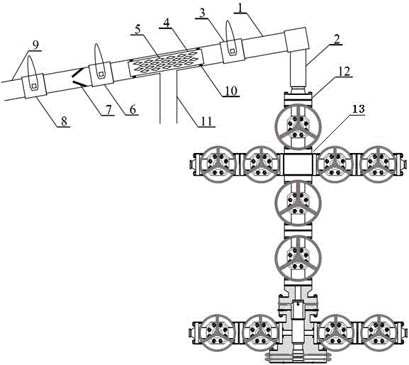
[0034] In order to overcome the existing defects in the existing ball catcher and its method of use, the present embodiment provides a figure 1 The large-diameter continuous ball catcher at the wellhead includes a cylindrical pipe section 1, the right side of which is connected to the wellhead pipeline 2, and the pipe section 1 is inclined 10° to 15° along the vertical direction of the wellhead pipeline 2. A safety cock 3, an isolation cock 6 and a ball collection cock 8 are sequentially arranged on the pipe section 1 from right to left, and a screen pipe 4 is arranged inside the pipe section 1 between the safety cock 3 and the isolation cock 6, The surface of the screen pipe 4 is provided with a plurality of flow holes 5 , the left side of the ball collection cock 8 is connected to the discharge pipeline 9 , and the pipe section 1 in the middle of the screen pipe 4 is connected to the discharge pipeline 11 .

[0035] Wherein, the inner diameter of the screen tube 4 is 85-90 m...

Embodiment 2

[0041] On the basis of Example 1, a spring sheet 7 is provided inside the pipe section 1 between the isolation cock valve 6 and the ball collection cock valve 8, and the spring sheet 7 is mainly used to prevent the pressure-suffocated ball passing through the isolation cock valve 6 from returning Drainage and backflow greatly improve the success rate of catching balls; at the same time, the spring leaf 7 is set on the left downstream of the isolation cock 6, which can be protected by the isolation cock 6 upstream on the right, and is intermittently impacted, prolonging the service life and reducing production costs .

[0042] For the stability and tightness between the screen pipe 4 and the pipe section 1 , the screen pipe 4 and the pipe section 1 are sealed and fixed by a sealing ring 10 .

[0043] The flow hole 5 is diamond-shaped, the distance between the parallel opposite sides of the flow hole 5 is 20-23 mm, and the acute angle between the sides of the rhombus is 40-45°. ...

Embodiment 3

[0045] On the basis of Embodiment 1 and Embodiment 2, this embodiment provides a method for controlling a large-diameter continuous ball catcher at the wellhead, including the following steps:

[0046] 1) Keep the safety cock 3 , the isolation cock 6 and the ball collection cock 8 in the closed state, and connect the wellhead pipeline 2 and the gas tree 13 through the upper flange 12 in the vertical direction.

[0047] 2) Start the blowout process of the gas tree 13, open the safety cock 3, and start the flowback of the pressure holding ball and the flowback fluid in the well.

[0048] 3) After spraying for 15 minutes, open the isolation cock 6 for 5 seconds, then close the isolation cock 6 again.

[0049] 4) Open the ball collection cock 8, and recover the pressure-suppressing balls discharged from the discharge line 9.

[0050] 5) Repeat steps 3) and 4) until all the pressure-suppressing balls in the well are recovered.

[0051] In the present invention, the wellhead pipel...


PUM

PropertyMeasurementUnit
The inside diameter ofaaaaaaaaaa

Abstract

The present invention provides a wellhead large-drift diameter continuous ball catcher, comprising a cylindrical pipe section. A wellhead pipeline is connected to the right side of the pipe section. The pipe section tilts downwards by 10 to 15 degrees in a vertical direction of the wellhead pipeline. A safety plug valve, an isolating plug valve and a ball collecting plug valve are orderly disposed on the pipe section from right to left. A screen pipe is disposed within the pipe section between the safety plug valve and the isolating plug valve, and a plurality of overflowing holes are formed in the surface of the screen pipe. A left side of the ball collecting plug valve is connected to a discharge pipeline. An open flow pipeline is connected to the pipe section in the middle of the screen pipe. The wellhead large-drift diameter continuous ball catcher overcomes the defects in the prior art, and is reliable in principle, and simple in structure; the ball catching method is feasible; continuous and efficient tripping ball collection can be achieved, and the safety production requirements of oil and gas fields are met; and powerful guarantee is provided for smooth construction of multi-stage ball sealer staged fracturing.

Description

technical field [0001] The invention relates to a drilling device, in particular to a large-diameter continuous ball catcher at the wellhead and a control method thereof. Background technique [0002] Many oil and gas reservoirs in China are characterized by the development of multi-layer systems. Practice has shown that multi-layer producing can effectively play the contribution of each production layer and improve single well production. Multi-layer partial pressure has become the key to increase single well production in this type of oil and gas reservoirs. [0003] The multi-stage ball-dropping segmental fracturing technology is a common technical means for multi-layer pressure division. This technology is to open the sliding sleeve of the closed fracturing section by putting in the pressure-holding ball of the corresponding size, and the pressure-holding ball and the ball seat of the sliding sleeve will slide down. And plug the fractured section. The pressure-holding b...

Claims


Application Information

Patent Timeline
IPC IPC(8): E21B31/00E21B43/26
Inventor 刘超赵振峰李宪文马旭张燕明来轩昂任发俊代东每朱礼明董时正沈磊问晓勇周长静马占国刘晓瑞
Owner PETROCHINA CO LTD
Why Eureka
Try Eureka