Supercharge Your Innovation With Domain-Expert AI Agents!

Light source module

A technology of light source module and light source assembly, which is applied in the direction of light source, electric light source, point light source, etc., can solve the problems of increased maintenance cost, damaged connector, complicated structure, etc., to simplify the structure, facilitate assembly and disassembly, reduce The effect of manufacturing cost

Inactive Publication Date: 2017-01-04
CORETRONIC (SUZHOU) CO LTD
View PDF8 Cites 0 Cited by
  • Summary
  • Abstract
  • Description
  • Claims
  • Application Information

AI Technical Summary

Problems solved by technology

[0004] However, the circuit board and the driving circuit board of the above-mentioned light source module are respectively equipped with a connector structure. In addition to the relatively complicated structure, the complex structure also leads to an increase in manufacturing cost. In addition, the circuit board of the light source module In the process of assembling and disassembling with the drive circuit board, it is quite easy to cause damage to the connector, which in turn leads to an increase in maintenance costs

Method used


Image

  • Light source module
  • Light source module
  • Light source module

Examples


Embodiment Construction

[0027] The aforementioned and other technical content, features and effects of the present invention will be clearly presented in the following detailed description of a preferred embodiment with accompanying drawings. The directional terms mentioned in the following embodiments, such as: up, down, left, right, front or back, etc., are only referring to the directions of the drawings. Accordingly, the directional terms are used to illustrate and not to limit the invention.

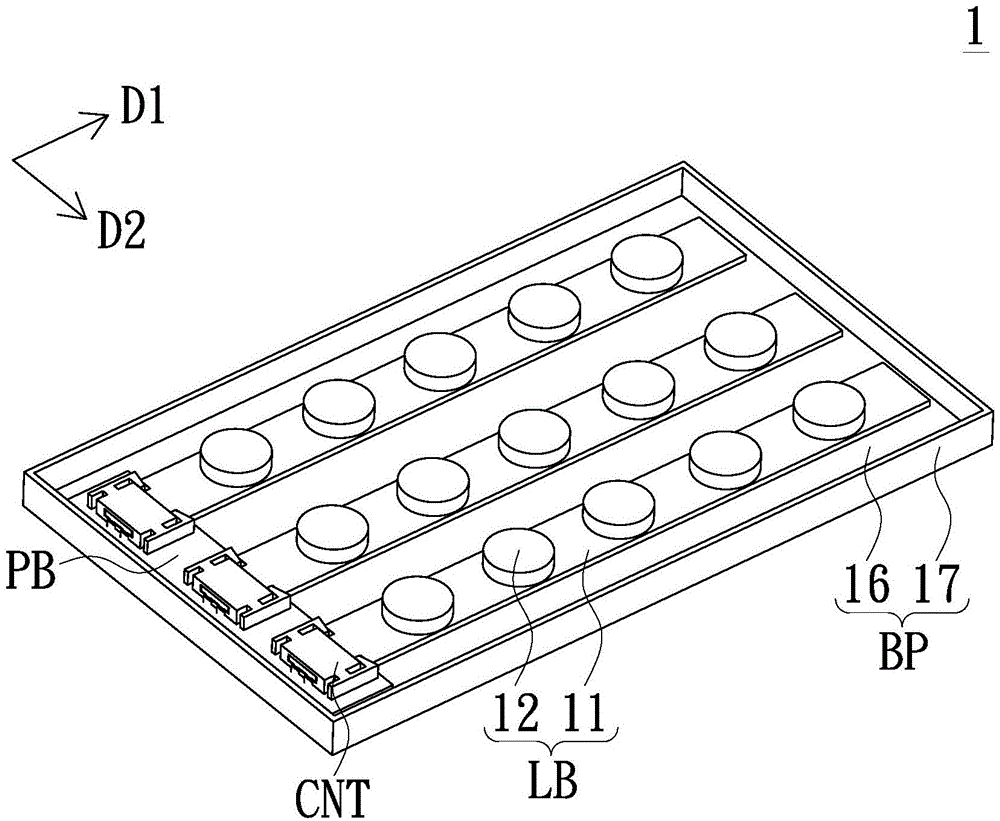
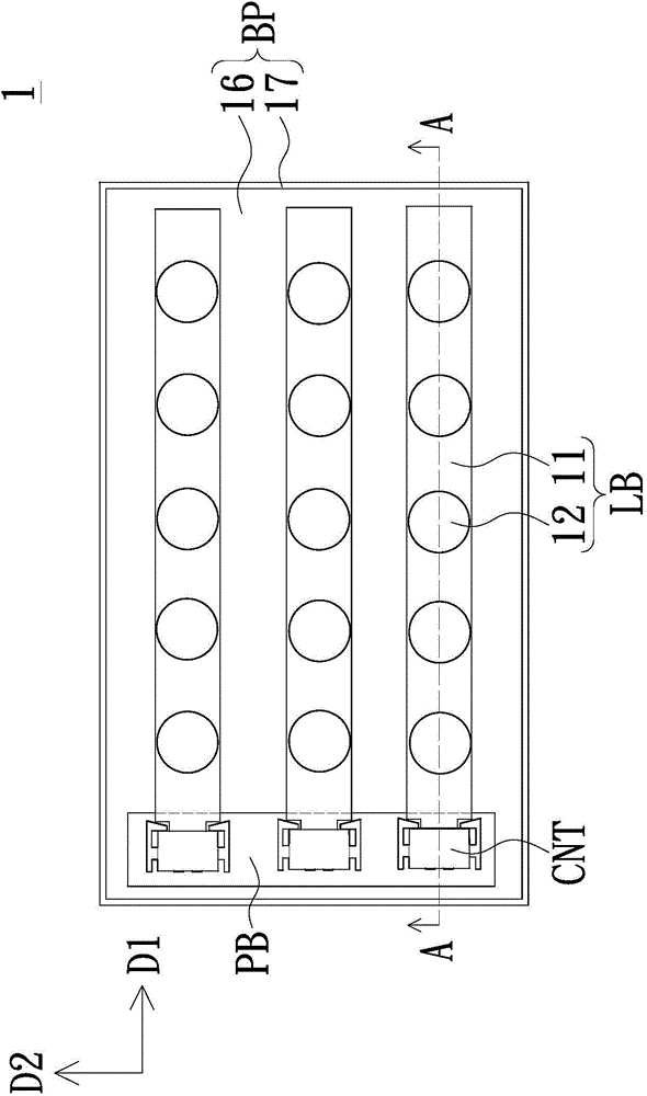
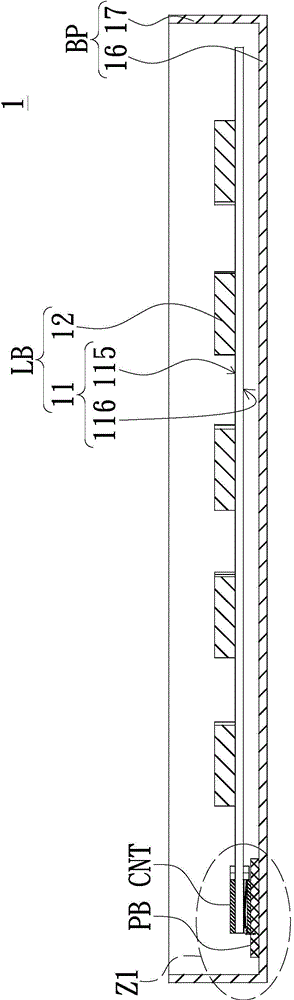
[0028] Such as Figure 1 to Figure 5 as shown, figure 1 It is a schematic diagram of the three-dimensional structure of the light source module according to an embodiment of the present invention. figure 2 for figure 1 A schematic top view of the light source module shown. image 3 for figure 2 Schematic cross-section along line AA. Figure 4 for image 3 An enlarged schematic view of the Z1 region of the structure shown. Figure 5 for figure 1 An exploded schematic diagram of some components of...


PUM


Abstract

The invention discloses a light source module. The light source module comprises at least one light source assembly and at least one connector. Each light source assembly comprises a first base plate and at least one light-emitting element. Each first base plate comprises a connecting end, a plate body part, at least one groove and a first electric connecting part. Each groove and the corresponding first electric connecting part are arranged at the corresponding connecting end. Each light-emitting element is allocated at the plate body part of the corresponding first base plate. Each groove is located between the corresponding light-emitting element and the corresponding first electric connecting part. The connectors are allocated at the connecting ends of the first base plates. Each connector comprises at least one fixing piece and a second electric connecting part. The fixing pieces are embedded into the grooves and used for fixing the first base plates. The second electric connecting parts are electrically connected with the first electric connecting parts. By means of the structures of the light source assemblies and the connectors of the light source module, assembling and disassembling of circuit boards are better facilitated.

Description

technical field [0001] The invention relates to a light source module, in particular to a light source module with a connector structure. Background technique [0002] A liquid crystal display mainly includes components such as a backlight module, a display panel, and a frame. Since the liquid crystal display itself is a non-self-luminous display, it is necessary to provide the required light source through the backlight module so that the display panel can provide a normal image with uniform brightness. According to the direction of the light source, the backlight module can be divided into an edge-type backlight module and a direct-type backlight module. [0003] Taking the direct-type backlight module as an example, the direct-type backlight module includes a backplane and a plurality of light source components arranged on the backplane. Each light source assembly includes a circuit board and a plurality of light emitting elements. These light-emitting elements are arr...

Claims


Application Information

Patent Timeline
IPC IPC(8): F21S8/00F21V19/00F21V23/06F21Y101/02
Inventor 魏朋伟
Owner CORETRONIC (SUZHOU) CO LTD
Features
  • R&D
  • Intellectual Property
  • Life Sciences
  • Materials
  • Tech Scout
  • Unparalleled Data Quality
  • Higher Quality Content
  • 60% Fewer Hallucinations
Learn More