
Lens, light emitting device and backlight module

A light-emitting device and lens technology, applied in the field of optics, can solve the problems of uneven lighting and over-brightness of backlight modules, and achieve the effect of increasing lighting uniformity

Inactive Publication Date: 2017-01-04
HONG FU JIN PRECISION IND (SHENZHEN) CO LTD +1
View PDF0 Cites 7 Cited by
  • Summary
  • Abstract
  • Description
  • Claims
  • Application Information

AI Technical Summary

Problems solved by technology

The brightness distribution of the light emitted by the backlight module is adjusted by the lens placed in front of the LED. However, the central area of ​​the existing backlight module using LEDs is usually too bright, which makes the entire backlight module emit uneven light.

Method used


Image

  • Lens, light emitting device and backlight module
  • Lens, light emitting device and backlight module
  • Lens, light emitting device and backlight module

Examples


Embodiment Construction

[0014] The embodiments of the present invention will be further described in detail below in conjunction with the accompanying drawings.

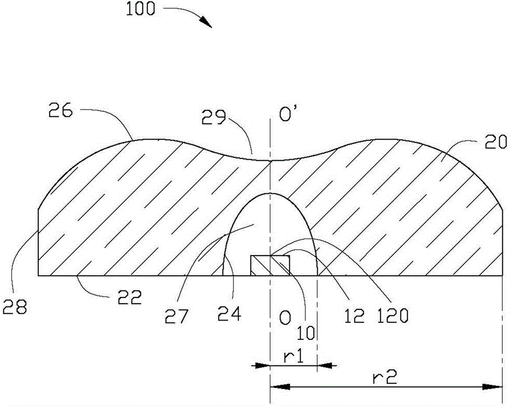
[0015] see figure 1 , the light emitting device 100 provided by the first embodiment of the present invention includes a light emitting unit 10 and a lens 20 . The lens 20 is located directly above the light emitting unit 10 and is used for controlling the light emitted by the light emitting unit 10 .

[0016] In this embodiment, the light emitting unit 10 is an LED that emits light toward the lens 20 . The light emitting unit 10 includes a light emitting surface 12 facing the lens 20 . The light emitting surface 12 has a center point 120 located in the center and a center axis OO' perpendicularly passing through the center point 120.

[0017] The lens 20 can be made of transparent material, such as plastic or glass. The plastic can be PMMA (polymethyl methacrylate), PC (polycarbonate, polycarbonate), or silicone. The lens 20 includes ...


PUM


Abstract

The invention provides a light incoming surface and a light emitting surface, which are located on the two sides away from each other of the lens and are symmetric with respect to the central axis of the lens. The light incoming surface and the light emitting surface are located in the same coordinate system. The light incoming surface meets a formula 1 (shown in the description), wherein C1 is the curvature of the light incoming surface, r1 is the distance between the center of the lens and the intersecting point between the light incoming surface and the radius perpendicular to the central axis of the lens, u1 is the normalized radius of the light incoming surface, am is the non-spherical coefficient, and Qm is an m polynomial representing that the sum of the am in the formula 1 is equal to the sum of the mean square root of the slope of the light incoming surface. The light emitting surface meets a formula 2 (shown in the description), wherein C2 is the curvature of the light emitting surface, r2 is the distance between the center of the lens and the intersecting point between the light emitting surface and the radius perpendicular to the central axis of the lens, u2 is the normalized radius of the light emitting surface, am is the non-spherical coefficient, Qm is an m polynomial representing that the sum of the am in the formula 2 is equal to the sum of the mean square root of the slope of the light emitting surface.

Description

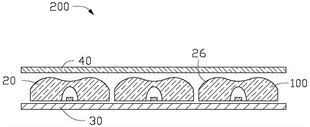
technical field [0001] The present invention relates to the field of optics, in particular to a lens, a light-emitting device with the lens, and a backlight module with the light-emitting device. Background technique [0002] Backlight modules, as light emitting devices, are widely used in liquid crystal displays of consumer electronic products such as mobile phones, computers, digital cameras, personal digital assistants, rear projection TVs, etc., for lighting up the liquid crystal displays. At present, with the development of display technology, more and more light emitting diodes (light emitting diodes, LEDs) are used as light sources in the backlight module. Generally, a plurality of LEDs in the backlight module are arranged in a matrix and correspond to the shape of the display panel in the liquid crystal display. The brightness distribution of the light emitted by the backlight module is adjusted by the lens placed in front of the LED. However, the central area of ​​...

Claims


Application Information

Patent Timeline
Patent Type & Authority Applications(China)
IPC IPC(8): F21V5/04F21V19/00F21V23/00F21Y101/02
CPCF21V5/046F21V19/001F21V23/00G02B19/0014G02B19/0061F21V5/04G02B3/02
Inventor 林柏宇林建辉余泰成
Owner HONG FU JIN PRECISION IND (SHENZHEN) CO LTD
Learn More