
Unmanned vehicle lane dynamic obstacle detection method

A technology for unmanned vehicles and dynamic obstacles, which is applied in the fields of autonomous driving and machine vision, and can solve the problems of low accuracy of detection results and delay in data processing.

Inactive Publication Date: 2017-01-04
张家港长安大学汽车工程研究院
View PDF5 Cites 44 Cited by
  • Summary
  • Abstract
  • Description
  • Claims
  • Application Information

AI Technical Summary

Problems solved by technology

[0004] The purpose of the present invention is to provide a method for detecting dynamic obstacles in the driveway of unmanned vehicles, so as to overcome the problems of delay in data processing and low accuracy of detection results encountered by laser sensors in detecting dynamic obstacles in outdoor environments

Method used


Image

  • Unmanned vehicle lane dynamic obstacle detection method
  • Unmanned vehicle lane dynamic obstacle detection method
  • Unmanned vehicle lane dynamic obstacle detection method

Examples


Embodiment Construction

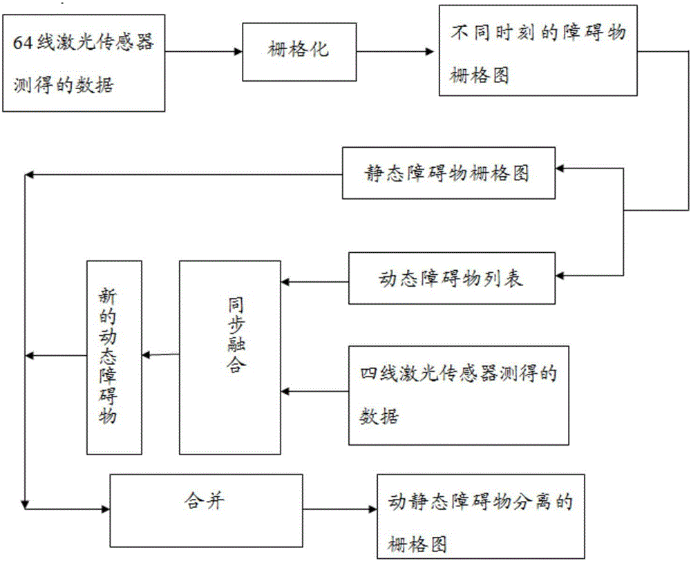
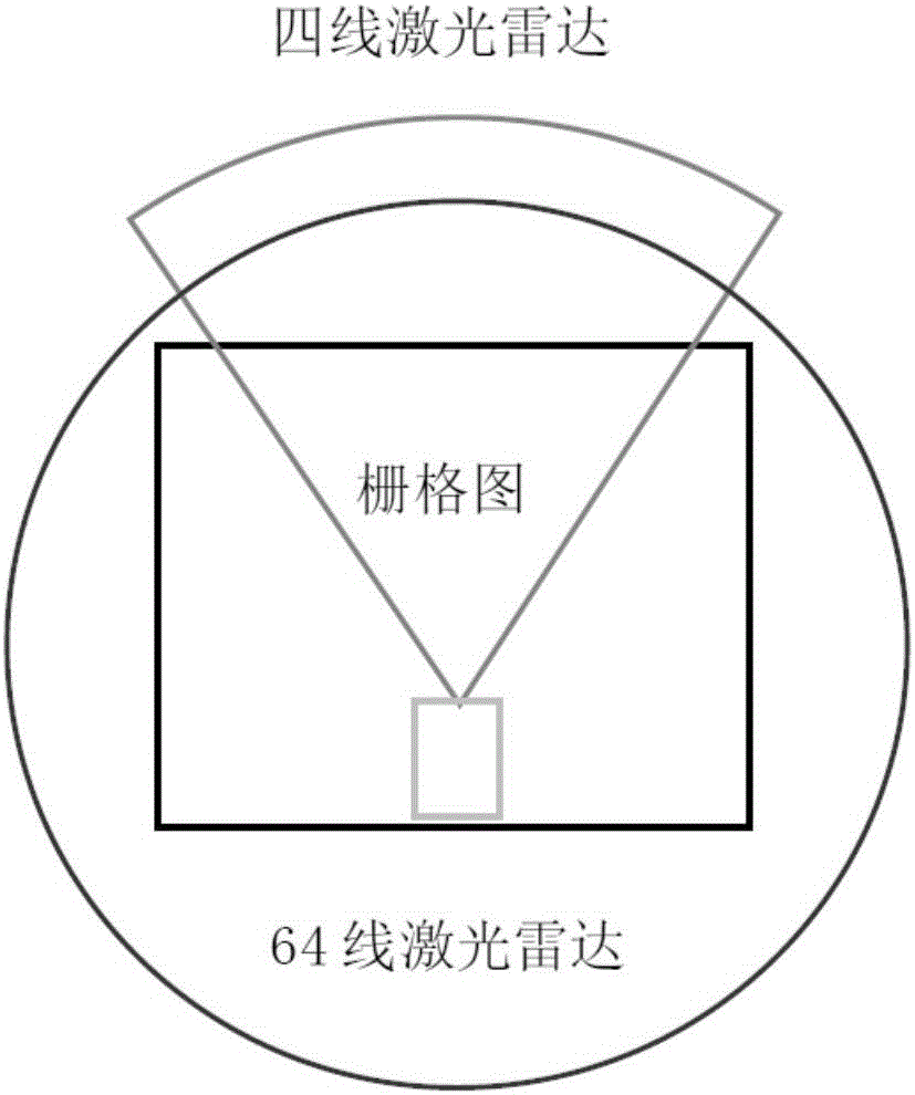
[0046] The embodiment of the present application discloses a method for detecting dynamic obstacles in the lane of an unmanned vehicle, including: 64 laser sensors, 4-line laser sensors, an information processing module, and an actuator. The method includes: matching and verifying the obstacle information obtained by fusing the information detected by the 64 laser sensors and the 4-line laser sensor, and sending a message to the actuator of the driverless car if the error is within the set accuracy range. The control instruction executes the driving control subsystem, which is used to generate a control instruction according to the collected auxiliary information, and controls the unmanned vehicle to perform corresponding operations.

[0047] Further, the obstacle information detected by the 64-line laser sensor and the four-line laser sensor will be fused, including obstacle shape, position, speed and other information, to improve the accuracy of obstacle detection.

[0048] ...


PUM


Abstract

The application discloses an unmanned vehicle lane dynamic obstacle detection method. The method comprises the steps of analyzing and processing the 64-wire laser data to detect and track the dynamic obstacles surrounding an unmanned vehicle; for a sector area in front of the unmanned vehicle having a higher accuracy, fusing a confidence distance theory with the 64-line laser data processing information and the motion state information outputted by the four-wire laser sensors to improve the detection accuracy of the obstacle motion states greatly; and then carrying out the time delay correction on the positions of the motion obstacles according to the fusion result; and finally, distinctively marking the positions occupied by the dynamic obstacles and the positions occupied by the static obstacles on an obstacle occupation grid map. According to the method, not only the obstacle motion information in an outdoor environment can be detected accurately, but also the dynamic obstacle position deviation brought by the sensor data processing time delay can be eliminated.

Description

technical field [0001] The present application relates to a method for detecting dynamic obstacles in an unmanned vehicle lane, which belongs to the fields of automatic driving and machine vision. Background technique [0002] With the continuous development of the economy and society, some social problems caused by the increase in the number of automobiles have become increasingly prominent, such as urban traffic, vehicle safety, energy supply, and environmental pollution. These realistic social problems all stem from the contradiction between the existing transportation infrastructure and the vehicle, which is not only reflected in traffic congestion, but also in environmental pollution and relatively backward roads caused by poor traffic. Potential safety hazards to people's lives and property caused by the state of the art and advanced vehicle technology. Nowadays, the loss of personnel and property caused by traffic accidents is becoming more and more serious in societ...

Claims


Application Information

Patent Timeline
Patent Type & Authority Applications(China)
IPC IPC(8): G01V8/10G01S17/93
CPCG01S17/931G01V8/10
Inventor 韩毅李广军王文宇许耀华
Owner 张家港长安大学汽车工程研究院
Learn More