Electric auto-lift sealed anti-theft switchgear

A technology for automatic lifting and power cabinets, applied in substation/distribution device shells, electrical components, substation/switch layout details, etc., can solve problems such as being easily damaged by criminals, affecting residents' lives, and damage to electrical equipment

Active Publication Date: 2017-01-04
STATE GRID CORP OF CHINA +3
View PDF4 Cites 2 Cited by
  • Summary
  • Abstract
  • Description
  • Claims
  • Application Information

AI Technical Summary

Problems solved by technology

[0002] With the continuous improvement of living standards, it also further promotes the continuous development of the power industry. In the power industry, the power cabinet is one of the essential equipment, so that all electrical equipment can be centrally controlled by the power cabinet, thereby further It facilitates the operation of electrical equipment. Most of the current power cabinets are set on the ground, and most of the power cabinets used now are simple cabinet structures, which can be used during the opening process. Open the door of the cabinet to further operate the electrical equipment in the power cabinet. Since the power cabinet is set on the ground, although the purpose of controlling the electrical equipment can be achieved, but because the power cabinet is set on the ground, it is possible to It will create opportunities for some lawbreakers in the society to take advantage of loopholes. Since most of the power cabinets used today are cabinet structures, they are easily damaged by criminals, thereby stealing the electrical equipment in the power cabinet. When the electrical equipment in the power cabinet is stolen, it will cause a large-scale power outage, and the current power cabinet will cause rainwater to pour into the power cabinet when there is a flood or heavy rain, thus damaging the electrical appliances. Equipment is damaged, which has a great impact on the lives of residents

Method used


Image

  • Electric auto-lift sealed anti-theft switchgear
  • Electric auto-lift sealed anti-theft switchgear
  • Electric auto-lift sealed anti-theft switchgear

Examples


Embodiment Construction

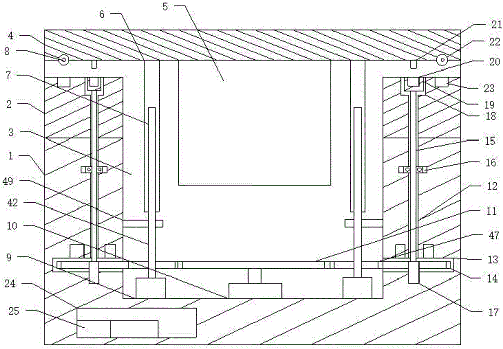
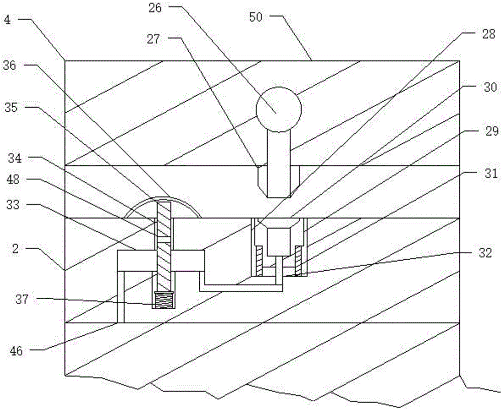
[0022] Such as Figure 1 to Figure 4 As shown, an electric power automatic lifting sealed anti-theft power cabinet includes a fixed base 1, a sealed base 2 is connected to the fixed base 1, and a concave-shaped The inner tank 3 of the base, the sealing base 2 is also connected with a sealing cover 4, the sealing cover 4 is connected with a power control cabinet 5 corresponding to the inner tank 3 of the base, and the inner tank 3 of the base is also connected A first gear 11 driven by a motor 10 is provided. The four corners of the power control cabinet 5 respectively include a support rod 6 connected to the sealing cover 4. The support rod 6 is respectively provided with a threaded hole 7, and the threaded A threaded support shaft 42 is respectively connected in the holes 7, and the threaded support shaft 42 rotates on the threaded shaft base 9 provided in the inner groove 3 of the base. 11 corresponds to the connected third gear 47. The four corners of the fixed base 1 and ...


PUM


Abstract

The present invention discloses an electric auto-lift sealed anti-theft switchgear. A fixed base is connected with a sealed base. The sealed base is further connected with a sealing cover. The sealing cover is connected with a power control cabinet corresponding to a base internal groove. The base internal groove is internally provided with a motor-driven first gear. A thread support shaft is connected with a third gear correspondingly connected with the first gear. A first rotating shaft is provided with a second gear correspondingly meshed and connected with the third gear. An end of the first rotating shaft is connected with a sealing end. The sealing cover is connected with a thread sealing shaft correspondingly meshed and connected with a thread shaft groove. The motor drives the first gear to rotate, so as to drive the thread support shaft to rotate, so that the sealing cover can be further lifted; and the sealing end is correspondingly connected with the thread sealing shaft disposed on the sealing cover, so that the theft is prevented.

Description

technical field [0001] The invention relates to a power cabinet, in particular to a power automatic lifting and sealing anti-theft power cabinet, in particular to an automatic lifting and sealing anti-theft power cabinet which can be sealed by a sealing cover and has an anti-theft function. Background technique [0002] With the continuous improvement of living standards, it also further promotes the continuous development of the power industry. In the power industry, the power cabinet is one of the essential equipment, so that all electrical equipment can be centrally controlled by the power cabinet, thereby further It facilitates the operation of electrical equipment. Most of the current power cabinets are set on the ground, and most of the power cabinets used now are simple cabinet structures, which can be used during the opening process. Open the door of the cabinet to further operate the electrical equipment in the power cabinet. Since the power cabinet is set on the gr...

Claims


Application Information

Patent Timeline
Patent Type & Authority Applications(China)
IPC IPC(8): H02B1/30H02B1/28
CPCH02B1/28H02B1/30H02B1/303H02B1/565H02B13/045
Inventor 左常亮
Owner STATE GRID CORP OF CHINA
Why Eureka
Try Eureka