Permanent magnet motor rotor and permanent magnet synchronous motor

A permanent magnet synchronous motor, permanent magnet motor technology, applied in synchronous motors with static armatures and rotating magnets, magnetic circuit rotating parts, magnetic circuits, etc., can solve the problem of low main pole permanent magnets, and improve the torque, reducing the risk of demagnetization, improving the effect of the operating point

Active Publication Date: 2019-09-03
GREE ELECTRIC APPLIANCES INC +1
View PDF7 Cites 0 Cited by
  • Summary
  • Abstract
  • Description
  • Claims
  • Application Information

AI Technical Summary

Problems solved by technology

[0004] Based on this, it is necessary to provide a method that can increase the operating point of the main pole permanent magnet and improve the anti-demagnetization ability in view of the low operating point of the main pole permanent magnet in the existing tangential permanent magnet motor and the risk of demagnetization. Permanent magnet motor rotor, and permanent magnet synchronous motor containing the above permanent magnet motor rotor

Method used


Image

  • Permanent magnet motor rotor and permanent magnet synchronous motor
  • Permanent magnet motor rotor and permanent magnet synchronous motor
  • Permanent magnet motor rotor and permanent magnet synchronous motor

Examples


Embodiment Construction

[0030] In order to make the purpose, technical solution and advantages of the present invention clearer, the permanent magnet motor rotor and the permanent magnet synchronous motor of the present invention will be further described in detail through the following embodiments and in conjunction with the accompanying drawings. It should be understood that the specific embodiments described here are only used to explain the present invention, not to limit the present invention.

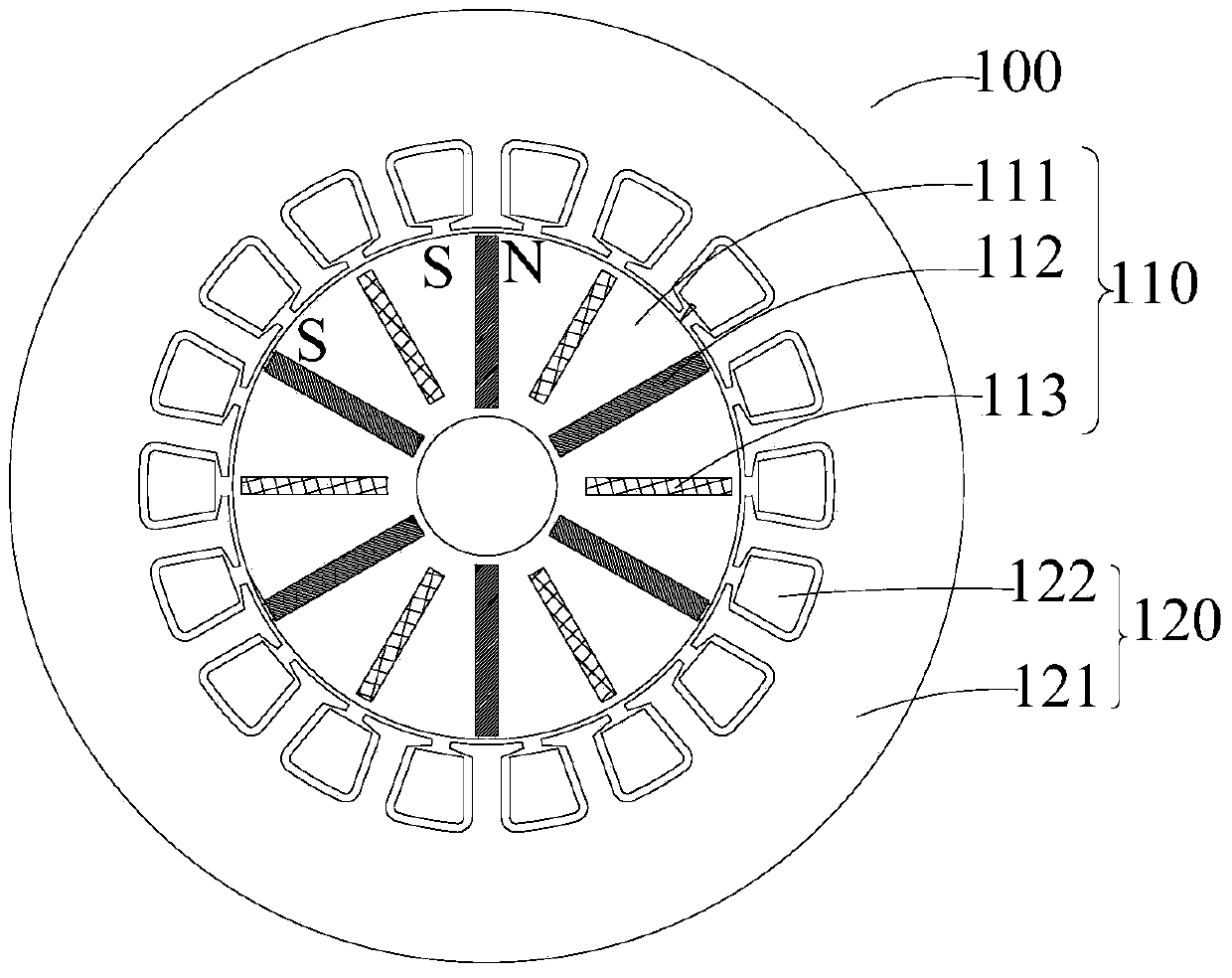
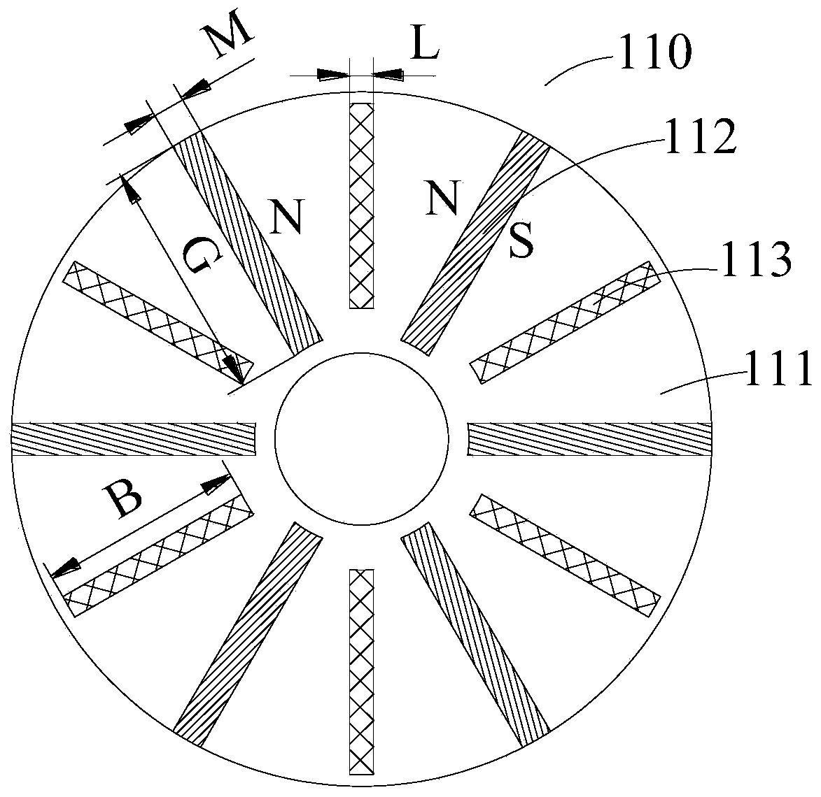
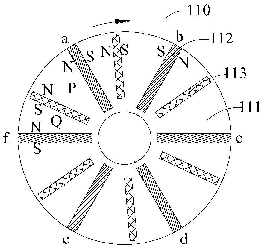
[0031] see figure 1 , the permanent magnet motor rotor 110 according to an embodiment of the present invention includes a rotor core 111 , a tangentially magnetized main pole permanent magnet 112 and a tangentially magnetized auxiliary permanent magnet 113 . The rotor core 111 is provided with an even number of placement slots, the even number of placement slots are evenly distributed along the circumferential direction of the rotor core 111 , and each placement slot is arranged along the radial directio...


PUM


Abstract

The invention provides a permanent magnet motor rotor and a permanent magnet synchronous motor. The permanent magnet motor rotor includes: a rotor core; tangentially magnetized main pole permanent magnets, the main pole permanent magnets are arranged along the radial direction of the rotor iron core, and the number of the main pole permanent magnets is synchronized with the permanent magnets The number of poles of the motor is equal, the main pole permanent magnets are evenly distributed along the circumferential direction of the rotor core, and the closest surface magnetic poles of any two adjacent main pole permanent magnets are the same; and tangentially magnetized An auxiliary permanent magnet, the auxiliary permanent magnet is arranged along the radial direction of the rotor core, and the auxiliary permanent magnet is located between any two adjacent main pole permanent magnets, so as to improve the The working point of the main pole permanent magnet is improved to reduce the risk of demagnetization.

Description

technical field [0001] The invention relates to the field of motor equipment, in particular to a tangential permanent magnet motor rotor and a permanent magnet synchronous motor containing the permanent magnet motor rotor. Background technique [0002] The motor with permanent magnet tangential magnetization structure can produce higher air gap flux density than the permanent magnet radial magnetization motor due to the "magnetic concentration" effect, so that the motor with permanent magnet tangential magnetization structure has a larger rotation speed. Torque / current ratio and torque / volume ratio, and motors with permanent magnet tangential magnetization structure are increasingly used in servo systems, electric traction, office automation, household appliances and other occasions. [0003] At present, because the two surfaces of a single permanent magnet provide the air gap flux at the same time in the tangential permanent magnet motor, the magnetic circuit is a parallel ...

Claims


Application Information

Patent Timeline
Patent Type & Authority Patents(China)
IPC IPC(8): H02K1/27
CPCH02K1/2766H02K1/2773H02K21/14H02K2201/00
Inventor 肖勇胡余生陈彬
Owner GREE ELECTRIC APPLIANCES INC
Why Eureka
Try Eureka