A power module for a power analyzer

A power module and power analysis technology, applied in the direction of instruments, electrical components, adjusting electrical variables, etc., can solve problems such as increasing the risk of errors, increasing workload, etc., to prevent device damage, eliminate ripple and noise, and increase output. The effect of power

Active Publication Date: 2018-10-30
CHNEGDU CHIFFO ELECTRONICS INSTR
View PDF7 Cites 3 Cited by
  • Summary
  • Abstract
  • Description
  • Claims
  • Application Information

AI Technical Summary

Problems solved by technology

When performing these complex tasks, multiple test instruments may be connected at the same time, thereby increasing the risk of errors; for this reason, engineers may choose automatic testing that is far more complicated than manual testing, but automated testing tasks will reduce manual errors, but writing and debugging programs further increase the workload of already overworked R&D engineers

Method used


Image

  • A power module for a power analyzer
  • A power module for a power analyzer
  • A power module for a power analyzer

Examples


Embodiment 1

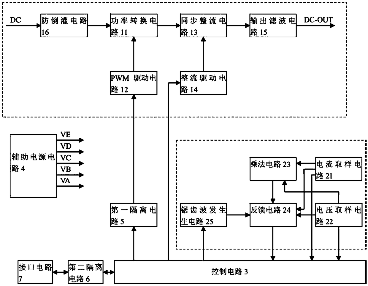
[0066] Embodiment 1: as figure 1 As shown, this embodiment provides a power module for a power analyzer, including a control circuit, a power conversion module, and a sawtooth wave module;

[0067] The sawtooth wave module includes a current sampling circuit, a voltage sampling circuit, a multiplication circuit, a feedback circuit, and a sawtooth wave generating circuit; the current sampling circuit and the voltage sampling circuit collect samples from the output end and / or the load end of the power conversion circuit current and sampling voltage, and sending the sampling current and sampling voltage to the multiplication circuit and the feedback circuit respectively;

[0068] The power conversion module includes a PWM drive circuit, a power conversion circuit, a rectification drive circuit, a synchronous rectification circuit and an output filter circuit;

[0069] The control circuit sends a sawtooth wave control signal to the sawtooth wave generation circuit to generate a r...

Embodiment 2

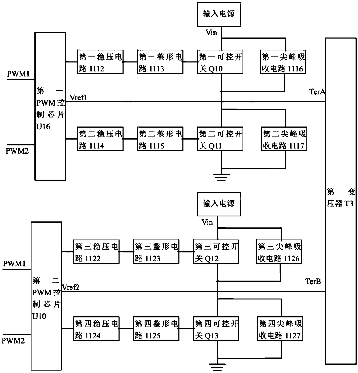
[0095] Embodiment 2: as Figure 3a , Figure 4a As shown, the difference between this embodiment and Embodiment 1 is that, in the first control circuit 111, a first PWM drive chip U16 is provided between the first controllable switch Q10 and the second controllable switch Q11. The voltage stabilizing circuit 1112, the first shaping circuit 1113; the first controllable switch Q10 and the first peak absorbing circuit 1116 are also connected in parallel between the power supply input end and the first end of the primary side of the first transformer T3; The second controllable switch Q11 and the second peak absorbing circuit 1117 are connected in parallel between the first terminal of the primary side of the first transformer T3 and the ground;

[0096] In the second control circuit 112, a second voltage stabilizing circuit 1114 and a second shaping circuit 1115 are further included between the second PWM drive chip U10 and the third controllable switch Q12 and the fourth contro...


PUM


Abstract

The invention relates to the field of power circuit, in particular to a power supply module for a power supply analyzer. On one hand, the power supply module provided by the invention uses the sampling current and the sampling voltage, combining the zigzag wave control signal issued by the control circuit, to generate zigzag waves in any specified waveforms. On the other hand, an anti-backflow circuit is arranged in the front end of the power conversion circuit to effectively prevent the device damages caused by the reverse current. A dummy load circuit is arranged at the output end of the power conversion circuit, to effectively solve the problem that when the output voltage is small, and the duty ratio of the PWM has decreased to the minimum value, if the power output is without load at this moment, since the energy storage inductance cannot work in the CCM mode, this will lead to the discontinuity of PWM, and will cause the unstable output shocks and larger ripple waves.

Description

technical field [0001] The invention relates to the field of power supply testing, in particular to a power supply module for a power analyzer. Background technique [0002] Usually, when conducting tests related to DC power supplies, engineers must assemble and configure multiple instruments to complete the DC power supply and measurement tasks. When performing these complex tasks, multiple test instruments may be connected at the same time, thereby increasing the risk of errors; for this reason, engineers may choose automatic testing that is far more complicated than manual testing, but automated testing tasks will reduce manual errors, but writing and debuggers add further workload to already overworked R&D engineers. The emergence of DC power analyzers avoids the need for engineers to use multiple devices and perform complex debugging before testing. The power analyzer can measure the current flowing into the DUT through its built-in current dynamic measurement capabil...

Claims


Application Information

Patent Timeline
Patent Type & Authority Patents(China)
IPC IPC(8): H02M3/155H02M1/32H02M1/14
CPCH02M1/14H02M1/32H02M3/155
Inventor 蒋承武管邦伟
Owner CHNEGDU CHIFFO ELECTRONICS INSTR
Why Eureka
Try Eureka