
Focus system and focus method

A focusing method and focal length technology, applied in the focusing system and focusing field, can solve the problems of slow data access, vibration, and inability to capture images, and achieve the effect of narrowing the search range

Inactive Publication Date: 2017-01-04
LUSTROUS ELECTRO OPTIC
View PDF5 Cites 4 Cited by
  • Summary
  • Abstract
  • Description
  • Claims
  • Application Information

AI Technical Summary

Problems solved by technology

However, due to the high pixels, the amount of data is too large, resulting in too slow data access speed, making it impossible to quickly capture images
In addition, portable electronic devices are mostly driven by voice coil motors (Voice Coil Actuator / Voice Coil Motor), so if they are driven quickly, they will cause vibration

Method used


Image

  • Focus system and focus method
  • Focus system and focus method
  • Focus system and focus method

Examples


no. 1 example 〕

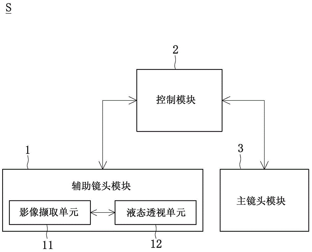
[0015] First, see figure 1 as shown, figure 1 It is a schematic block diagram of a simple module of the focusing system S of the embodiment of the present invention. The first embodiment of the present invention provides a focus system S, which includes an auxiliary lens module 1, a control module 2, and a main lens module 3. For example, the focus system S provided by the present invention can be set on an electronic device devices such as smartphones, tablets, etc.

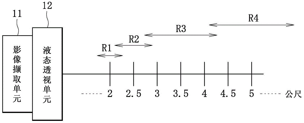
[0016] Next, if figure 1 As shown, the auxiliary lens module 1 may include an image capture unit 11 and a liquid lens unit 12 , and the image capture unit 11 and the liquid lens unit 12 are electrically connected to each other. The control module 2 is electrically connected to the auxiliary lens module 1 and the main lens module 3 , so that the control module 2 controls the auxiliary lens module 1 and the main lens module 3 . In addition, the liquid lens unit 12 has multiple focus range settings. It should b...

no. 2 example

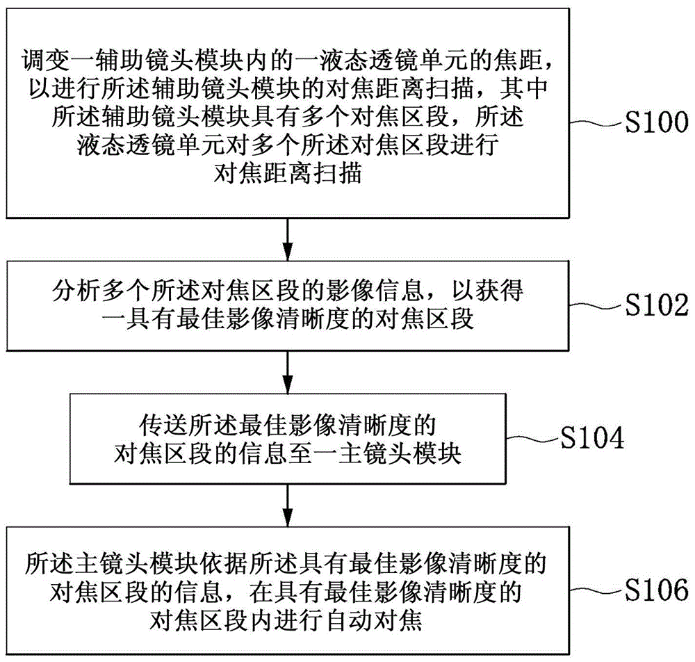
[0025] First, see figure 2 and at the same time cooperate figure 1 as shown, figure 2 It is a schematic flowchart of the steps of the focusing method according to the second embodiment of the present invention. The second embodiment of the present invention provides a focusing method for fast focusing. As shown in step S100, the focal length of a liquid lens unit 12 in an auxiliary lens module 1 is adjusted to scan the focus distance of the auxiliary lens module 1, wherein the auxiliary lens module 1 has a plurality of focus segments, The liquid lens unit 12 performs focus distance scanning on a plurality of focus segments. For example, the liquid lens unit 12 can be controlled by a control module 2 to adjust the focusing distance from far to near or from near to far. In addition, in other implementations, the way of adjusting the focal length of the liquid lens unit 12 can also be a single focus adjustment, a continuous focus adjustment, a focus adjustment scan in a pre...


PUM

PropertyMeasurementUnit
Resolutionaaaaaaaaaa

Abstract

The invention discloses a focus system and a focus method. The focus method comprises the steps of adjusting focal distance of a liquid state lens unit in an auxiliary lens module, thereby scanning the focus distance of the auxiliary lens module, wherein the auxiliary lens module is equipped with multiple focus sections, and the liquid state lens unit carries out focus distance scanning on the multiple focus sections; analyzing the image information of the multiple focus sections, thereby obtaining the focus section with the optimum image definition; transmitting the information of the focus section with the optimum image definition to a master lens module; and carrying out automatic focus in the focus section with the optimum image definition by the master lens module according to the information of the focus section with the optimum image definition. The invention also provides a focus system.

Description

technical field [0001] The invention relates to a focusing system and a focusing method, in particular to a focusing system and a focusing method capable of fast focusing. Background technique [0002] With the advancement of technology, today's portable electronic devices, such as smart phones, tablet computers, etc., have more and more functions. In addition to making calls with mobile devices, users can also use them to capture images. [0003] Common portable electronic devices mostly adopt passive auto-focus and have only one lens. In addition, with the development of the trend, the image pixels of portable electronic devices are getting higher and higher. Generally speaking, the frame rate (Frame Rate) of portable electronic devices with 8 to 10 million pixels, or even 20 million pixels. About 25 ~ 30FPS or so. However, because the pixels are too high, the amount of data is too large, and the speed of data access is too slow, making it impossible to quickly capture ...

Claims


Application Information

Patent Timeline
IPC IPC(8): H04N5/232G02B7/38G03B13/34
Inventor 蔡智伟
Owner LUSTROUS ELECTRO OPTIC
Learn More