Resource distribution method and apparatus

A technology of resource allocation and resource allocation unit, applied in the field of resource allocation, can solve problems such as restricting the development of D2D communication, and achieve the effect of improving coverage

Inactive Publication Date: 2017-01-04
ZTE CORP
View PDF3 Cites 64 Cited by
  • Summary
  • Abstract
  • Description
  • Claims
  • Application Information

AI Technical Summary

Problems solved by technology

However, the existing technology does not provide a solution for D2D UEs (including D2D Relay UEs) to simultaneously serve multiple UEs within one PSCCH cycle in a D2D scenario, which will undoubtedly limit the development of D2D communication.

Method used


Image

  • Resource distribution method and apparatus
  • Resource distribution method and apparatus
  • Resource distribution method and apparatus

Examples


Embodiment 2

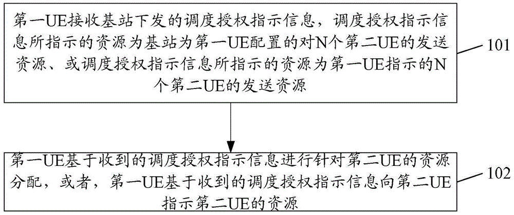
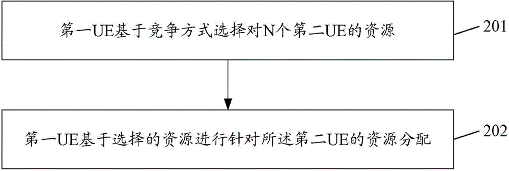
[0085] A resource allocation method provided by Embodiment 2 of the present invention, such as figure 2 As shown, the method mainly includes:

[0086] In step 201, the first UE selects resources for N second UEs based on contention.

[0087] The first UE described in this embodiment of the present invention may be a D2D relay UE, or may be a D2D UE that simultaneously supports multiple transmissions. That is to say, the first UE described in the embodiment of the present invention can support serving N second UEs at the same time.

[0088] Step 202, the first UE performs resource allocation for the second UE based on the selected resource;

[0089] Wherein, N is an integer greater than or equal to 1; the resources include at least PSCCH resources and PSSCH resources, the PSCCH is the physical control channel of the Sidelink link, the PSSCH is the Physical Shared Channel of the Sidelink link, and the Sidelink link is A link established between UEs for device-to-device D2D c...

Embodiment 3

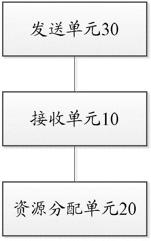
[0097] The resource allocation device provided by Embodiment 3 of the present invention is applied to the first UE, such as image 3 As shown, the device mainly includes:

[0098] The receiving unit 10 is configured to receive scheduling grant indication information issued by the base station, where the resource indicated by the scheduling grant indication information is the transmission resource for N second UEs configured by the base station for the first UE, or the resource indicated by the base station. The resources indicated by the scheduling grant indication information are the transmission resources of the N second UEs indicated by the first UE;

[0099] The resource allocation unit 20 is configured to perform resource allocation for the second UE based on the received scheduling grant indication information, or indicate the second UE to the second UE based on the received scheduling grant indication information H;

[0100] Wherein, N is an integer greater than or eq...

Embodiment 4

[0109] An apparatus for resource allocation provided by Embodiment 4 of the present invention is applied to the first UE, such as Figure 4 As shown, the device mainly includes:

[0110] A selection unit 40, configured to select resources for N second UEs based on contention;

[0111] A resource allocation unit 50, configured to perform resource allocation for the second UE based on the selected resource;

[0112] Wherein, N is an integer greater than or equal to 1; the resources include at least PSCCH resources and PSSCH resources, the PSCCH is the physical control channel of the Sidelink link, the PSSCH is the Physical Shared Channel of the Sidelink link, and the Sidelink link is A link established between UEs for device-to-device D2D communication.

[0113] Wherein, the PSCCH resources are N PSCCH resources with continuous frequencies, and the PSSCH resources are PSSCH resources with continuous subframe domains.

[0114] In an embodiment, the resource allocation unit 50 ...


PUM


Abstract

The invention discloses a resource distribution method. The method comprises the following steps that a first user equipment (UE) receives scheduling authorization indication information issued by a base station, wherein a resource indicated by the scheduling authorization indication information is a sending resource which is configured for the first UE by the base station for N second UE, or the resource indicated by the scheduling authorization indication information is a sending resource of the N second UE, and the sending resource is indicated by the first UE; and the first UE carries out resource distribution for the second UE on the basis of the received scheduling authorization indication information, or the first UE indicates the resource of the second UE to the second UE on the basis of the received scheduling authorization indication information, wherein the N is an integer which is greater than or equal to 1; the resource at least includes a PSCCH resource and a PSSCH resource, a PSCCH is a physical control channel of a Sidelink link and a PSSCH is a physical sharing channel of the Sidelink link, and the Sidelink link is a link established between the UE of device-to-device D2D communication. The invention also discloses a resource distribution apparatus.

Description

technical field [0001] The present invention relates to the field of device-to-device (D2D, Device-to-Device) communication, in particular to a resource allocation method and device. Background technique [0002] In a cellular system, when there is a service to be transmitted between two user equipments (UE, User Equipment), the service data from user equipment 1 (UE1) to user equipment 2 (UE2) will first be transmitted to the cell where UE1 is located through the air interface The base station (Base Station, or called evolved base station (eNB, evolved eNB)), the base station transmits the service data to the base station of the cell where UE2 is located through the core network, and the base station transmits the above service data to UE2 through the air interface. The service data transmission from UE2 to UE1 adopts a similar processing flow. [0003] In fact, with the diversification of mobile communication services, for example, social networking, electronic payment, e...

Claims


Application Information

Patent Timeline
Patent Type & Authority Applications(China)
IPC IPC(8): H04W72/04H04W72/12
CPCH04W72/0446H04W72/12H04W72/23H04W72/04
Inventor 王文焕吴栓栓杨瑾黄双红袁明
Owner ZTE CORP
Why Eureka
Try Eureka