Inflatable umbrella easy to inflate and deflate
A technology for inflating and deflating umbrellas, applied in the field of umbrellas, can solve problems such as inability to realize technical problems, inability to realize solutions, and increased difficulty in winding
- Summary
- Abstract
- Description
- Claims
- Application Information
AI Technical Summary
Problems solved by technology
Method used
Image
Examples
Embodiment 1
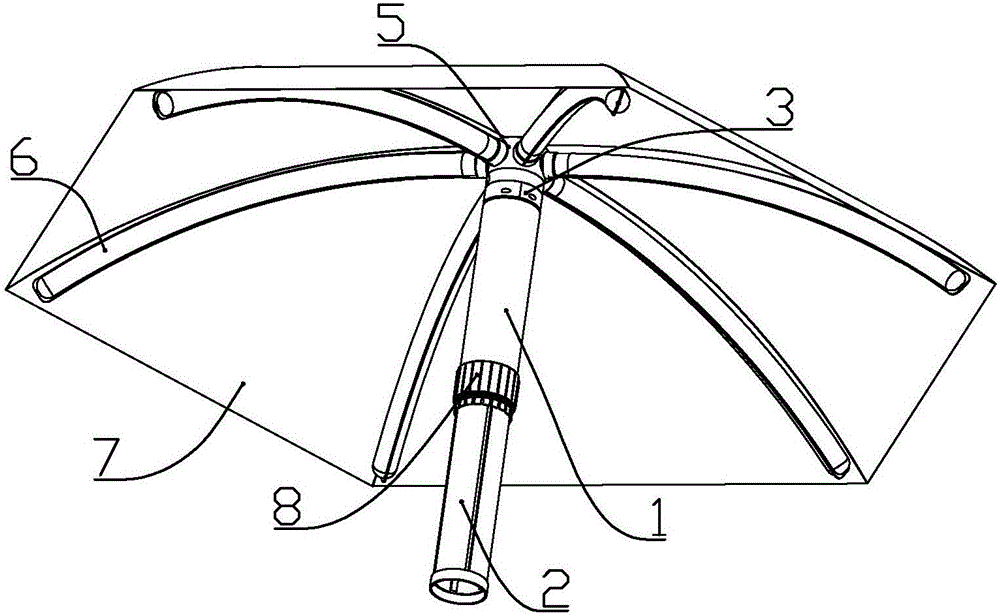
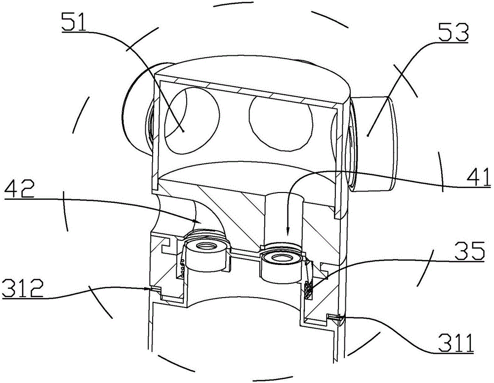
[0052] according to Figure 1 to Figure 21 As shown, this embodiment is an inflatable umbrella that is easy to inflate and deflate. It includes an umbrella handle 1, a push tube 2 connected below the umbrella handle, a rotating joint 3 rotatably connected to the upper part of the umbrella handle, fixedly connected to the rotating The gas control part 4 at the upper end of the joint, the umbrella frame fixing part 5 fixedly connected to the upper end of the gas control part, the inflatable support tube 6 arranged on the outer periphery of the umbrella frame fixing part, and the umbrella connected to the upper end of the inflatable support tube Face 7.
[0053] The upper part of the push cylinder is fixedly connected with a piston 22 which is slidably connected to the inner wall of the umbrella handle; the side wall of the push cylinder is located below the piston and is formed with a guide groove 23 arranged along the length of the push cylinder; Evenly distributed in the circumf...
Embodiment 2
[0071] according to Figure 1 to Figure 21 As shown, this embodiment is an inflatable umbrella that is easy to inflate and deflate. It includes an umbrella handle 1, a piston 2 slidably connected to the inner wall of the umbrella handle, and an umbrella surface connector rotatably connected to the upper part of the umbrella handle , And a hollow umbrella surface or a plurality of inflatable support tubes 6 connected to the umbrella surface connector and communicated with the umbrella surface connector; when the umbrella surface connector is connected to an inflatable support tube, each inflatable support tube is connected Umbrella 7;
[0072] The lower end of the outer wall of the umbrella handle is formed with a plurality of splints 17 uniformly arranged in the circumferential direction; a compression gap 171 is formed between the two adjacent splints; the outer side of the lower part of the umbrella handle is threaded with a twisting part 8; The lower part of the inner wall of...
Embodiment 3
[0076] according to Figure 22 As shown, the difference between this embodiment and Embodiment 1 is that the lower part of the inflatable support tube 6 is also connected with a first support rod 6a, a second support rod 6b, and a third support rod 6c from outside to inside; the first support rod 6a. The second support rod 6b and the third support rod 6c are hollow airbags; the inner end 6c of the third support rod is closed, and the other end is connected to the inflatable support tube; one end of the first support rod 6a is connected to the The outer end of the inflatable support tube is in communication, and the other end is in communication with the middle of the second support rod 6b; one end of the second support rod 6b is in communication with the inflatable support tube, and the other end is close to the closed end of the third support rod 6c. The position is connected; after the airbag is inflated, the lower first support rod 6a, the second support rod 6b, and the third...
PUM
 Abstract
Description
Claims
Application Information
 - R&D Engineer
- R&D Manager
- IP Professional
- Industry Leading Data Capabilities
- Powerful AI technology
- Patent DNA Extraction
Browse by: Latest US Patents, China's latest patents, Technical Efficacy Thesaurus, Application Domain, Technology Topic, Popular Technical Reports.
© 2024 PatSnap. All rights reserved.Legal|Privacy policy|Modern Slavery Act Transparency Statement|Sitemap|About US| Contact US: help@patsnap.com


