Pipe bender

A tube bending machine and copper tube technology, which is applied in the direction of feeding devices, manufacturing tools, metal processing, etc., can solve the problems of speed influence, achieve fast feeding speed, shorten production cycle, and avoid bending and wearing copper tubes.

Inactive Publication Date: 2017-01-11
JDM JINGDA MASCH (NINGBO) CO LTD
View PDF6 Cites 14 Cited by
  • Summary
  • Abstract
  • Description
  • Claims
  • Application Information

AI Technical Summary

Problems solved by technology

The traditional long U pipe bending machine needs to go through the straightening link when feeding, and it is straightened by the straightening wheel, and the feeding method is through the friction of leather strips, so the speed will be affected.

Method used


Image

  • Pipe bender
  • Pipe bender
  • Pipe bender

Examples


Embodiment Construction

[0034] The present invention will be further described in detail below in conjunction with the accompanying drawings and embodiments.

[0035] like figure 1 As shown, a pipe bending machine includes a frame 1 , a full circle part 2 , a feeding part 3 , a motor 4 , a bending die mechanism 5 , a bending frame 6 , a cutting part 7 , and a mandrel part 8 .

[0036] The full circle part 2 , feeding part 3 , bending die mechanism 5 and cutting part 7 are installed on the frame 1 , and the mandrel part 8 is installed on the bending frame 6 of the bending mechanism 5 .

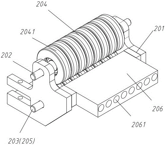
[0037] like figure 2 As shown, the full-circle component 2 includes a full-circle wheel bracket 201 , an upper full-circle wheel shaft 202 and a lower full-circle wheel shaft 203 , an upper full-circle wheel 204 and a lower full-circle wheel 205 , and a material guide plate 206 . The two ends of the upper full-circle wheel shaft 202 and the lower full-circle wheel shaft 203 are respectively supported by the full-ci...


PUM


Abstract

The invention discloses a pipe bender which comprises a rack, a rounding part, a feeding part, a die bending mechanism, cutting parts and a core shaft part; the rounding part, the feeding part, , the cutting parts and the die bending mechanism are sequentially installed on the rack; the feeding part is composed of a clamping part and a transmission part for transmitting the clamping part; the clamping part clamps and loosens a copper pipe and moves through the transmission part and enables the copper pipe to move to a position capable of being bended after clamping the copper pipe; the die bending mechanism rotates 180 degrees to bend the pipe and process the pipe into a U-shaped pipe after tightly clamping the pipe; the core shaft part is composed of a core shaft, a core shaft sleeve, a moving seat and a moving seat driver; the core shaft penetrates through the core shaft sleeve; the front end of the core shaft and the core shaft sleeve are fixed together; the core shaft sleeve penetrates through a front core shaft sleeve clamp and can move therein; the front core shaft sleeve clamp is fixed to a bending frame of the die bending mechanism; the back part of the core shaft sleeve is closely fit by a back core shaft sleeve clamp; and the back core shaft sleeve clamp is fixed to the moving seat.

Description

technical field [0001] The invention relates to a pipe bending machine. Background technique [0002] Long U tube bending machine is used to produce long U tube, which is an important part of air conditioner heat exchanger. The traditional long U pipe bending machine needs to go through the straightening link when feeding, and it is straightened by the straightening wheel, and the feeding method is through the friction of leather strips, so the speed will be affected. Contents of the invention [0003] The technical problem to be solved by the present invention is to provide a pipe bending machine that overcomes the above-mentioned defects of the prior art, so that its speed is faster. [0004] The technical solution adopted by the present invention to solve the problems of the technologies described above is: [0005] A pipe bending machine, including a frame, a full-circle part, a feeding part, a bending assembly, and a cutting part; It includes a full circle wheel br...

Claims


Application Information

Patent Timeline
Patent Type & Authority Applications(China)
IPC IPC(8): B21D9/05B21D3/14B21D3/00B21D35/00B21D43/10B21D43/28B21C51/00
CPCB21D9/05B21C51/00B21D3/00B21D3/14B21D35/002B21D43/10B21D43/28
Inventor 龚俊君杨旭升金恒亮
Owner JDM JINGDA MASCH (NINGBO) CO LTD
Why Eureka
Try Eureka