
Combined tool for machining of brake cylinder

A technology of brake wheel cylinder and composite tool, which is applied in the direction of manufacturing tools, metal processing equipment, milling cutters, etc., can solve the problems of low work efficiency, high labor intensity, long processing time, etc., and achieve high work efficiency and low labor intensity. , the effect of reducing the replacement steps

Inactive Publication Date: 2017-01-11
厦门永裕机械工业有限公司
View PDF13 Cites 2 Cited by
  • Summary
  • Abstract
  • Description
  • Claims
  • Application Information

AI Technical Summary

Problems solved by technology

[0004] Therefore, the present invention provides a composite tool for brake cylinder processing, which mainly solves the need for a specific tool for different parts or processes in the prior art, resulting in long processing time, high cost, low work efficiency, and high labor intensity. and other technical issues

Method used


Image

  • Combined tool for machining of brake cylinder
  • Combined tool for machining of brake cylinder
  • Combined tool for machining of brake cylinder

Examples


Embodiment Construction

[0021] In order to make the purposes, technical solutions and advantages of the embodiments of the present invention clearer, the technical solutions in the embodiments of the present invention will be clearly and completely described below with reference to the accompanying drawings in the embodiments of the present invention. Obviously, the described embodiments These are some embodiments of the present invention, but not all embodiments. Based on the embodiments of the present invention, all other embodiments obtained by those of ordinary skill in the art without creative efforts shall fall within the protection scope of the present invention.

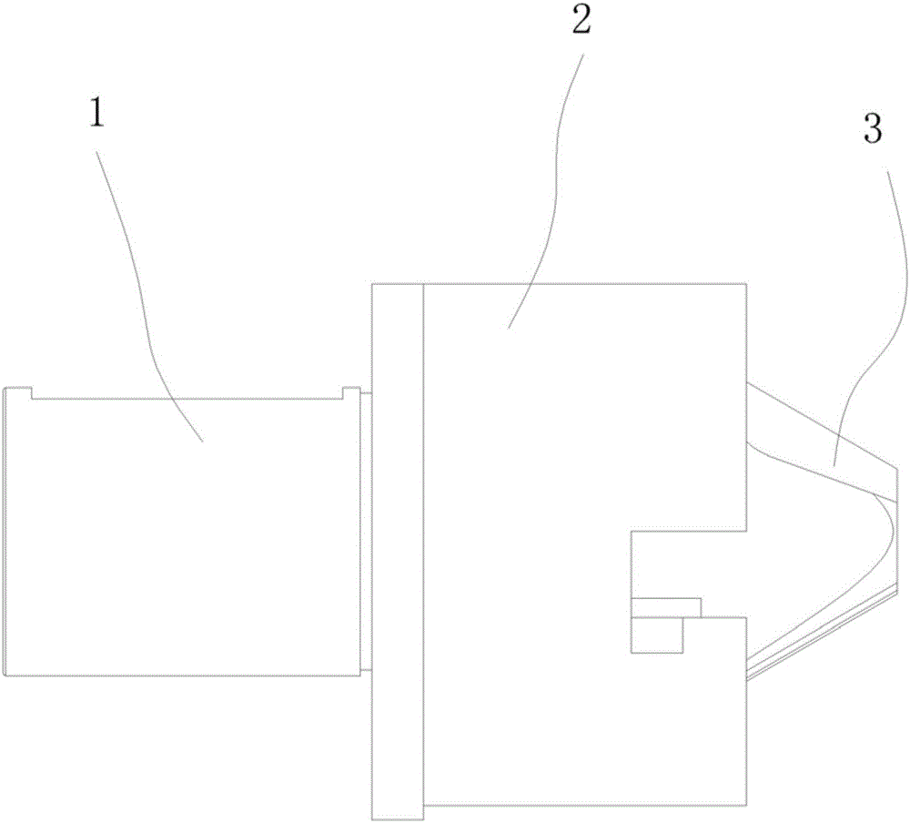
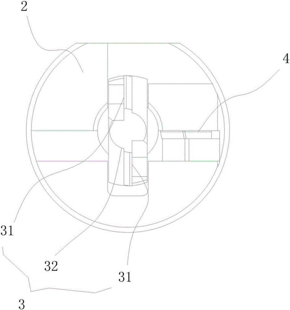
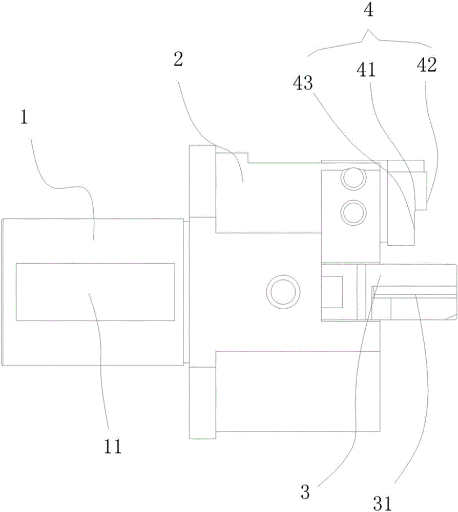
[0022] like Figure 1 to Figure 4 As shown, a composite tool for machining a brake wheel cylinder includes a convex shaft 1, a connecting disc 2 and a composite tool group connected in sequence. The composite tool group includes a milling surface chamfering tool 3 and an outer diameter milling chamfering tool 4. Specifically: the c...


PUM


Abstract

The invention discloses a combined tool for machining of a brake cylinder, and the combined tool can achieve surface milling, external diameter milling and chamfering at a time. The combined tool for machining of the brake cylinder comprises a cam shaft, a connecting plate and a combined tool set which are connected in sequence. The combined tool set comprises a surface milling and chamfering tool and an external diameter milling and chamfering tool. The surface milling and chamfering tool is located in the center of the connecting plate, is a sheet tool and is provided with an inclined side blade, and the end of the surface milling and chamfering tool is provided with a surface milling cut-over blade. The inclined side blade is matched with an inner hole chamfer of the brake cylinder to be machined, so that a molding blade achieving inner hole milling and chamfering simultaneously is formed. The external diameter milling and chamfering tool is located at the edge of the connecting plate and spaced from the surface milling and chamfering tool, so that a tool structure molding the center and the external diameter portion of the brake cylinder simultaneously is formed.

Description

technical field [0001] The invention relates to a machining tool for machining a brake wheel cylinder, in particular to a composite tool for machining a brake wheel cylinder which can mill surfaces, outer diameters and chamfers at one time. Background technique [0002] The brake system is a more important part of the car body. The brake cylinder, commonly known as the brake caliper, is the final part of the brake system that produces the braking effect. When the brake pedal is stepped on, the brake fluid is squeezed and controlled by the brake. The dynamic master cylinder distributes the pressure to each brake cylinder through the brake fluid pipeline. Due to the incompressibility of the liquid, the brake cylinder pushes the brake pads and the brake disc to rub against the brake fluid pressure to generate friction. braking action. [0003] At present, in the process of brake cylinder processing, the processing of the nozzle hole of the cylinder requires four processes to c...

Claims


Application Information

Patent Timeline
Patent Type & Authority Applications(China)
IPC IPC(8): B23C5/12B23C3/12
CPCB23C3/126B23C5/12
Inventor 翁泽民
Owner 厦门永裕机械工业有限公司
Learn More