Eureka AIR delivers breakthrough ideas for toughest innovation challenges, trusted by R&D personnel around the world.

Punching equipment with drill bit convenient to replace

A drill bit and punching technology, which is applied in the direction of drilling/drilling equipment, metal processing equipment, boring machine/drilling machine parts, etc., can solve the problem of reducing the power transmission efficiency of power components, the inability to improve the cleaning work of the work surface, and the waste is not easy to be Clean up problems such as coming out, achieve good power transmission efficiency, reduce replacement steps, and prolong service life

Inactive Publication Date: 2021-02-05
范甬挺
View PDF7 Cites 0 Cited by
  • Summary
  • Abstract
  • Description
  • Claims
  • Application Information

AI Technical Summary

Problems solved by technology

[0003] Traditional punching equipment generally drives the drilling parts through a belt. However, the belt produces plastic deformation after a period of use, thereby reducing the power transmission efficiency of the power parts and easily causing slippage between the punching parts and the workpiece to be processed. , In addition, the processed waste is all over the workbench, and the waste from the corners of the workbench is not easy to be cleaned out, so the cleaning work of the workbench cannot be perfected

Method used


Image

  • Punching equipment with drill bit convenient to replace
  • Punching equipment with drill bit convenient to replace
  • Punching equipment with drill bit convenient to replace

Examples


Embodiment Construction

[0025] In order to make the technical means, creative features, goals and effects achieved by the present invention easy to understand, the present invention will be further described below in conjunction with specific embodiments.

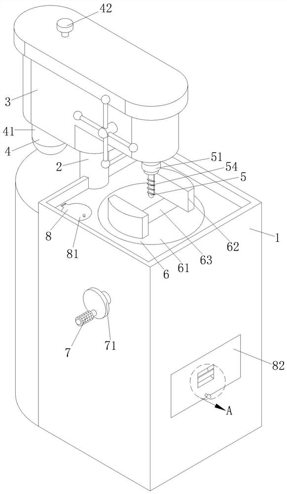
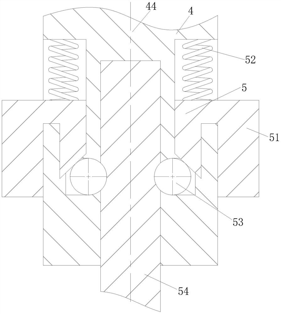
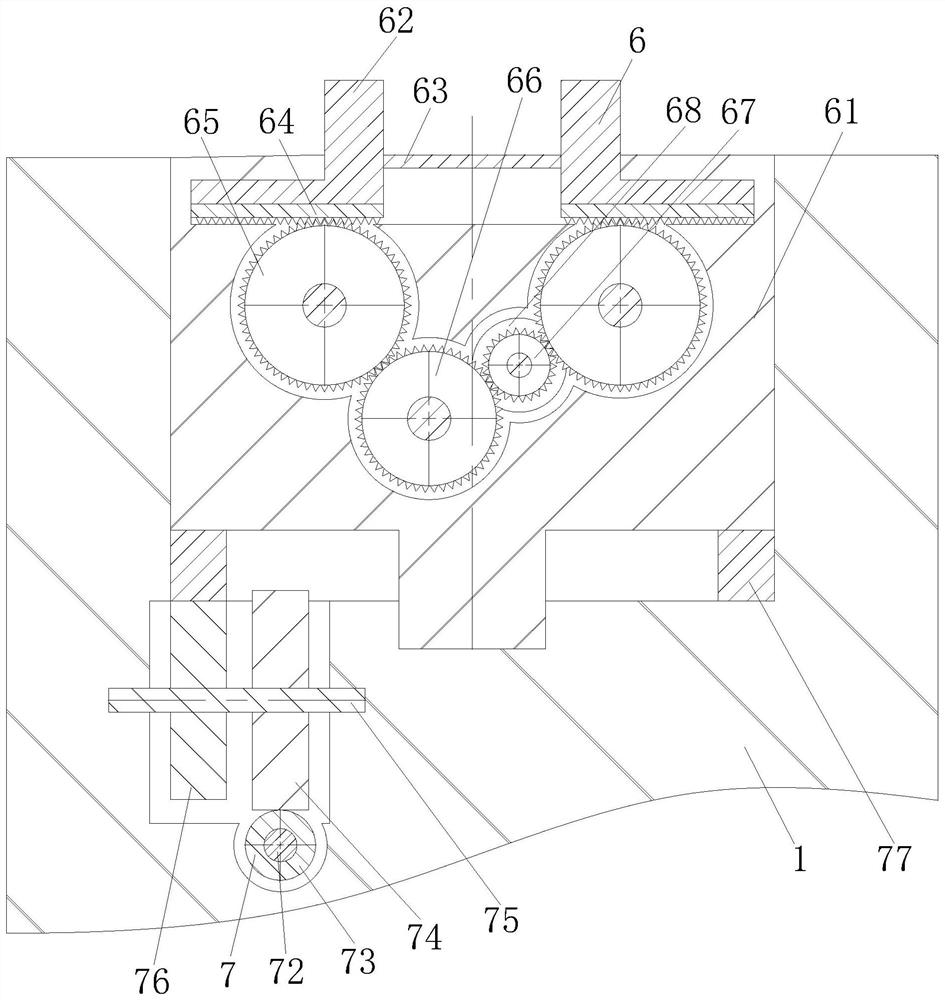
[0026] Such as Figure 1-Figure 8 As shown, a punching device for conveniently replacing drill bits according to the present invention includes a placement table 1, a support column 2, a main body 3, a transmission mechanism 4, a quick change mechanism 5, a clamping mechanism 6, an angle mechanism 7 and a storage Mechanism 8, the support column 2 is fixed on the top of the placement table 1, the main body 3 slides on the top of the support column 2, and the transmission mechanism 4 for driving the quick change mechanism 5 for drilling Located inside the main body 3, the quick-change mechanism 5 for quick replacement of drilling parts is arranged at the bottom of the main body 3, and the quick-change mechanism 5 is connected to the transmission mec...


PUM


Abstract

The invention relates to the field of punching equipment, in particular to punching equipment with a drill bit convenient to replace. The punching equipment comprises a placement table, a support column, a main body, a transmission mechanism, a quick replacement mechanism, a clamping mechanism, an angle mechanism and a containing mechanism. The service life of a power transmission component can beprolonged through the arrangement of the transmission mechanism, so that the use cost is saved, the economic benefits are improved, a damaged drilling execution component can be conveniently and quickly replaced through the arrangement of the quick replacement mechanism, the replacement efficiency is improved, and a part needing to be machined can be conveniently and automatically fixed through the arrangement of the clamping mechanism, the part is prevented from sliding during machining, the machining precision is improved, the angle of a machined component is conveniently adjusted through the arrangement of the angle mechanism, the precision and the position of a hole site obtained by the part needing to be machined are controlled within the required range, waste can be conveniently collected into a storage component through arrangement of the containing mechanism, and recycling of the waste is facilitated.

Description

technical field [0001] The invention relates to the field of punching equipment, in particular to a punching equipment for conveniently replacing drill bits. Background technique [0002] Punching equipment refers to the general name of machinery and equipment that leaves cylindrical holes or holes on the target by means of rotary cutting or rotary extrusion using a tool that is harder and sharper than the target. Also known as drilling rigs, punching machines, drilling machines, through-hole machines, etc. The desired effect is achieved by drilling precision parts. Punching equipment includes semi-automatic punching equipment and fully automatic punching equipment. With the increase in human resource costs; most companies consider fully automatic punching equipment as the development direction . With the development of the times, the drilling technology of automatic punching equipment has improved, and the advantages of using fully automatic punching equipment to drill va...

Claims


Application Information

Patent Timeline
Patent Type & Authority Applications(China)
IPC IPC(8): B23Q3/155B23B47/00B23Q3/06B23Q3/12B23Q11/00
CPCB23B47/00B23Q3/06B23Q3/12B23Q3/155B23Q11/0042
Inventor 范甬挺
Owner 范甬挺
Why Eureka
Eureka Blog
Learn More