

Method for processing piston inner cavity of middle cylinder
A technology of piston inner cavity and processing method, which is applied in the field of breaker processing, can solve the problems of inseparable stability of fixed structure, reduce eccentricity, poor operability, etc. Effect
- Summary
- Abstract
- Description
- Claims
- Application Information
AI Technical Summary
Problems solved by technology
Method used
Image

Examples
Embodiment 1
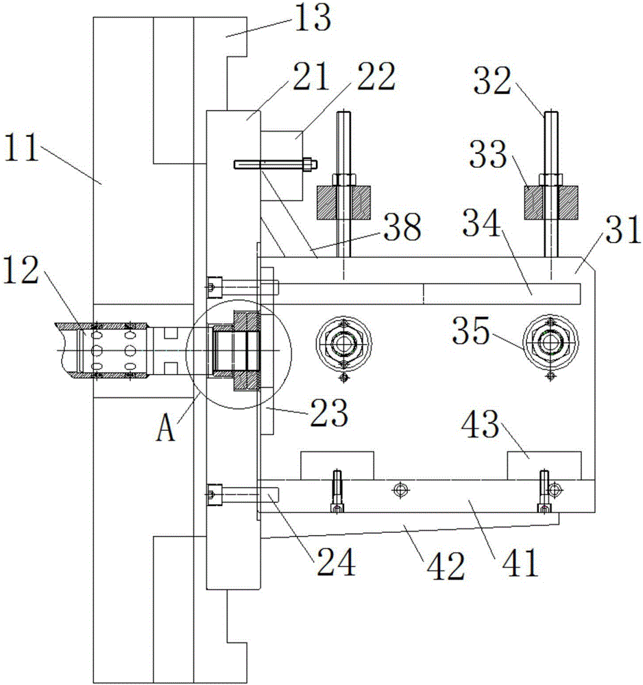
[0046] combine figure 2 , the processing method of a kind of middle cylinder piston cavity of the present embodiment adopts the cylinder body fixing mechanism to carry out the processing of piston cavity, and the cylinder body fixing mechanism is connected with the support disk 11 on the turning shaft 12 of the lathe, and the cylinder body is fixed The mechanism includes connecting plate 21, side wall baffle plate 31 and supporting plate 41 which are vertically fixed to each other, that is, side wall baffle plate 31 and supporting plate 41 are all perpendicular to connecting plate 21, and are fixedly connected with connecting plate 21, as figure 2 As shown in , the supporting plate 41 is arranged horizontally, the side wall baffle 31 is arranged vertically, and the lower end of the side wall baffle 31 is fixedly connected with the supporting plate 41 . The middle section of the supporting plate 41 passes through the axis of the rotating shaft 12 , and the two side wall baffl...
Embodiment 2
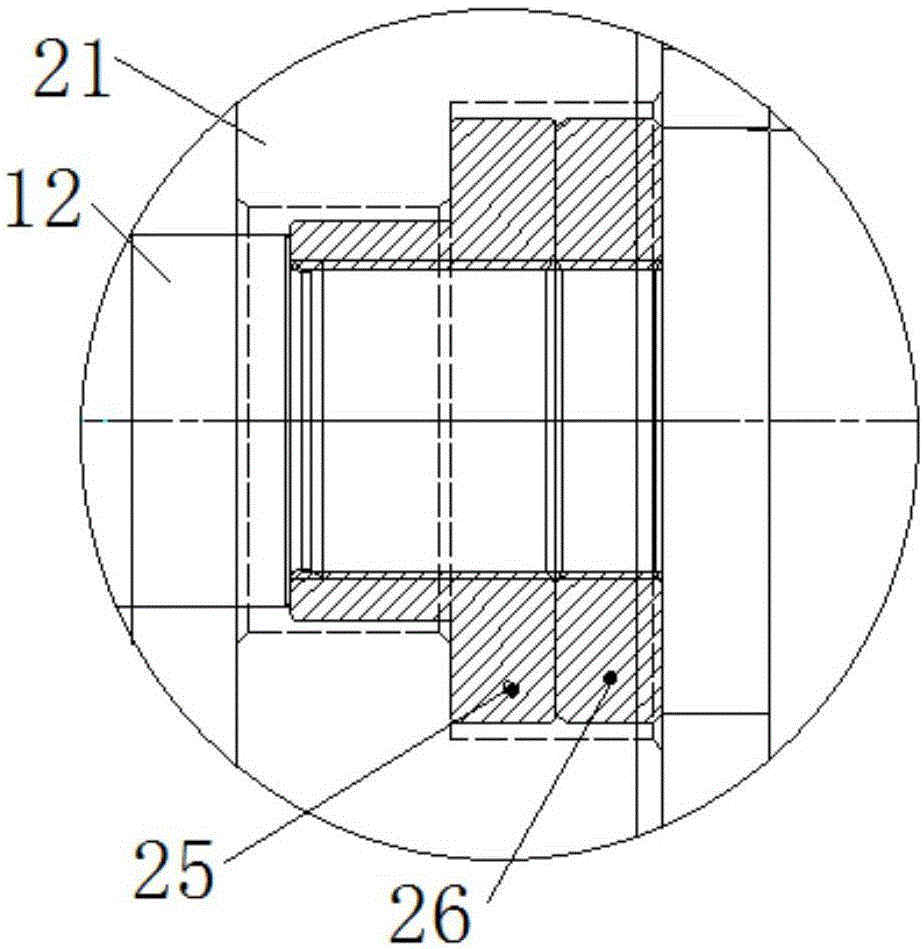
[0051] The basic structure of the cylinder fixing mechanism in this embodiment is the same as that in Embodiment 1, the difference is that four end face reference blocks 23 are arranged on the connection plate 21, and the distance between the end face reference blocks 23 and the axis of the rotating shaft 12 is the same , the end face reference blocks 23 are equally spaced along the circumferential direction, that is, the central angle between two adjacent end face reference blocks 23 is 90°.
[0052] The upper surface of the supporting plate 41 is provided with a bottom reference block 43, such as figure 2 As shown in , the bottom reference block 43 is arranged in two rows along the length direction of the pallet, and the position of the bottom reference block 43 and the position of the pressure plate 33 correspond up and down. When the pressing force is applied by the pressure plate 33, the bottom of the middle cylinder is Supported by the reference block 43, the point of a...
Embodiment 3
[0058] The basic structure of the cylinder fixing mechanism in this embodiment is the same as that of Embodiment 2, the difference is that: Figure 5 , in the present embodiment, a reinforcement bolt 24, a first rib 34 and a second rib 38 are arranged between the side wall baffle 31 and the connection plate 21, and the second rib 38 is perpendicular to the side wall baffle 31; the first rib The plate 34 is connected to the surface where the screw rod 32 is located on the side wall baffle plate 31 . The first rib 34 and the second rib 38 fix the side wall baffle from different directions, and the height of the second rib 38 from the supporting plate 41 is greater than the height of the axis of the piston hole relative to the supporting plate 41, which is closer to the overall structure The central position, the support strength is higher.
[0059] In order to reduce the overall weight, the side wall baffle 31 is provided with a first lightening hole 39, such as Image 6 As sh...
PUM
 Abstract
Description
Claims
Application Information